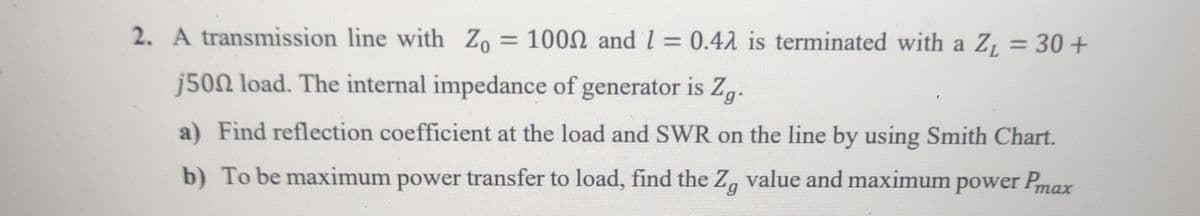
2. A transmission line with Zo = 1000 and 1 = 0.42 is terminated with a Z₁ = 30+ j500 load. The internal impedance of generator is Zg. a) Find reflection coefficient at the load and SWR on the line by using Smith Chart. b) To be maximum power transfer to load, find the Zg value and maximum power Pmax


Q: Find "" for t > 0 if the circuit is in steady state at t = 0-
A: In the given question we need to calculate the current i .
Q: Problem 7-5: Design an active-RC first-order high-pass filter for a cutoff frequency of 10 kHz and…
A: According to questions, we need to design active RC first order high pass filter for a cutoff…
Q: Assume that the circuit in the figure has L equal to 0.700 H. R equal to 450 92, and C equal to 3.50…
A:
Q: Discuss the effect of the value of K on the system in terms of Percentage overshoot, peak time,…
A: It is asked to discuss the effects of the value of K on the system in terms of percentage overshoot,…
Q: When the switch is in position 2, the circuit will discharge the capacitor. Draw the circuit for…
A: see the attachment please.Explanation:
Q: The specific resistance is defined as Select the correct response: Resistance of any conductor at 20…
A: The specific resistance is defined as------a. Resistance of any conductor at 20 degrees Celsius.b.…
Q: Find the Laplace transform of each of the following functions: Y (s) =(e^−4s )/(s^2 + 6s + 5)
A: The Laplace transform is a powerful mathematical tool used in engineering, physics, and other fields…
Q: A line to ground fault occurs on the terminals of an alternator, sequence voltages and sequence…
A: The given data is shown below:
Q: Three charged particles are located at the corners of an equilateral triangle as shown in the figure…
A:
Q: Consider the following transfer function: C(s) = S+1 as ocs +1 where a is a given positive number…
A: The transfer function is :
Q: An electron moves in the xy-plane with a speed of 106 m/s. Its velocity vector makes an angle of 60°…
A: 8×10-16 NExplanation:
Q: Determme the ((I) rms value {(x) rms value clue of the following wartforms: """(+)
A: In the given questions we need to calculate the RMS and average value of the following signal.
Q: 2. Use Kirchhoff's Laws to find the current flowing in the circuit. 1 V 10 Ω 8 V ли 20 Ω Hill 7 V -…
A: Kirchhoff's Voltage Law (KVL) is a fundamental principle in electrical engineering used to analyze…
Q: ladder diagram for one lampholder and one duplex receptacle controlled by a Single Pole Switch.
A: The objective of this question is to create a ladder diagram for an electrical circuit that includes…
Q: A telegraph source has two symbols (dot and dash). The time of dot is 0.5 sec, the time of dash is 3…
A: Given:Number of symbols = 2.Time of dot, ,Time of dash, Time between symbols, Probability, we need…
Q: If Vs = 8 V, R1 = 13 Q2 and R2 = 62 2, what voltage would you expect to see displayed on a voltmeter…
A: Voltage divider rule, is a fundamental principle in electrical engineering used to determine the…
Q: Needs Complete typed solution with 100 % accuracy. Don't use chat gpt or ai i definitely…
A: The objective of the question is to find the inductance (L) of the LCR circuit at the resonant…
Q: QUESTION 4 R C S Select the correct timing diagram for the gated S-R latch shown above. 1 3 t t CSRO…
A: In the given question we need to find the correct timing diagram.
Q: This is a practice problem from my Introduction to Electronics course. Could you please walk me…
A: Answered the common emitter configurationExplanation:Step 1:Step 2:
Q: 2. Given the following circuit: w R1 R2 R3 3Ω >60 2Ω MW V1 V2 V3 4V -14V 4V For circuit above, solve…
A:
Q: Q1: For the circuit shown below, without modifying any sign or direction, find the total power…
A: The circuit diagram,
Q: Please now solve p2 of this question
A: we need to answer above question.
Q: Consider the circuit shown in the figure. w R 90.0 Ω 10.0 Ω a b 10.0 Ω 90.0 Ω (a) Let the equivalent…
A: The circuit diagram is shown below,
Q: Please answer in typing format
A: Given:A=3V, B=6V, C=2V, D=6VWe have to calculate the value of
Q: 5.2-4 A message signal m(t) is normalized to peak voltages of ±1 V. The average message power equals…
A:
Q: Please show how it would look on that graph please use the given graph
A: Given minterms are Given graph is,Asked to show how it would look on that graph.
Q: Q8. Show the resultant of the two waves yi A sin [wt-k(x+Ax)] Y2A sin (wt-kx) 2Acos (kAx/2) sin…
A: To find the resultant of the two waves y1 and y2,We can add them together y = y12
Q: A FM signal has a carrier frequency of 105 MHz and upper frequency is 105.007 MHz of modulated…
A: The given data is shown below:
Q: The DC biasing circuit of a BJT amplifier circuit is shown in Fig. Q7. The BJT Qi has ẞ = 75 and the…
A: Please refer below page if u have any doubt please feel free to ask meExplanation:Step 1: Step 2:…
Q: V₁(t) + R1 www ix(t) C₁ R₂ Given the element values v₁ (t) = 18cos(210³t) V, R1 = 700 £2, R2 = 1400…
A: The given circuit isR1=700 Ω.R2=1400 Ω.C1=120 nF.The supply voltage is⇒v1(t)=18cos(2π103t), V.We…
Q: For the circuit below, solve the current through R3 and power dissipated from R3 Using a. Thevenin…
A: Thevenin's Theorem states that any linear electrical network with multiple voltage and current…
Q: 2.1
A: W=21CV2Explanation:The energy stored in a capacitor can be calculated using the formula:…
Q: 1. The following are the input signals of a Balanced Modulator v1 = 8 sin[2π(200 x 10³)t] and V2 = 3…
A: (a) s(f) = -6j s(f - 200.2 * 103) + 6j s(f + 200.2 * 103) + 6j s(f - 199.8 * 103) -6j s(f + 199.8 *…
Q: Q1-Determine the nodal voltages for the circuit of Fig. 1, using the bottom node as the reference…
A: Given circuit diagram
Q: Three impedances of 5 + j 12, 8j7 and 3 - j12 ohms are connected in star to red, yellow and blue…
A: In this question, we need to determine the line currents. phase sequence is RYB
Q: 1- The no-load current drawn by transformer is usually, the per cent of the full-load current is a)…
A: The no-load current drawn by transformer is usually the percent of the full-load current is ---a.…
Q: 5. +5v- R1 www V1 10V R5 www 2 mW R2 6kQ .5 mA R3 www R4 2kQ R₁ R₂ 22 22 Rs Total R(KQ) V(v) I(mA)…
A: Given a circuit and asked to fill in the table according to the circuit.
Q: 2.4
A: Detailed solution is peovided below.Explanation:
Q: 1.6
A: •Energy stored in inductor is 45×10^-6 × e^(600/5)t J. •The solved answer is given below if you have…
Q: a b -b- A coil with a 10.800 cm and b = 13.000 cm is in the same plane with a long straight wire.…
A: We have,To calculate the emf in the loop at t=8 sec
Q: Question 1 4.5 V 2 V 1.2.V a) Determine if JBE and JBC are forwards bias or reverse bias b) What is…
A: The objective of the question is to determine the biasing of the junctions JBE and JBC in a Bipolar…
Q: The power applied to R1 is calculated theoretically (hand calculation) and the voltage and current…
A: In this question, we need to determine the power applied to the resistance R. Power applied to the…
Q: find the convolution of the unit impulse f(t) =u(t) -u(t-1) with itself
A:
Q: Question 7: Three capacitors having capacitances 20 μF, 30 uF and 40 μF are connected in series with…
A: The given data is shown below
Q: For each circuit provided, fully solve and complete the associated table.
A:
Q: Q) Joint pdf of (X, Y) is given by: f(x, y) = = 95 0 + y²) 0 ≤ x ≤ 1,0 ≤ y ≤ 1 Compute the…
A: The probability is determined by integrating with respect to x and y and substituting the limit of x…
Q: Use nodal analysis to find V, in the circuit below. 3 mA ( 10 kn 21, 10 kn
A: The circuit diagram,
Q: What is the thevenin voltage and resistance of the circuit below across nodes a and b? Node b is…
A: Vth=50 V, Rth=6 ohmExplanation:Step 1:Step 2:Step 3:Step 4: Thevenin Circuit:
Q: For the below combinational-logical circuit, derive the Boolean equation of the output 'f'? Note:…
A:
Q: find gain, input, and out lut resistance. VDD M2 RD Vin M₁ Чем з 3 o Vout C
A: The objective of the question is to find the gain, input resistance, and output resistance of a…

Unlock instant AI solutions
Tap the button
to generate a solution
Click the button to generate
a solution
- A single-phase overhead transmission line consists of two solid aluminum conductors having a radius of 3 cm with a spacing 3.5 m between centers. (a) Determine the total line inductance in mH/m. (b) Given the operating frequency to be 60 Hz, find the total inductive reactance of the line in /km and in/mi. (c) If the spacing is doubled to 7 m, how does the reactance change?A small manufacturing plant is located 2 km down a transmission line, which has a series reactance of 0.5/km. The line resistance is negligible. The line voltage at the plant is 4800V(rms). and the plant consumes 120kW at 0.85 power factor lagging. Determine the voltage and power factor at the sending end of the transmission line by using (a) a complex power approach and (b) a circuit analysis approach.In terms of line-to-line capacitance, the line-to-neutral capacitance of a single-phase transmission line is Same Twice One-half
- A Z0 = 50 Ω transmission line of length l = 4.25 m (with dielectric material with parameters εr = 4, µr = 1) is attached to a time-harmonic generator (V0rms = 30 V, Rg = 20 Ω f = 75 MHz). The line is terminated with a load ZL = 100 + j50 Ω. Find the complex instantaneous voltages and currents along the line and time-averaged losses in the load and generator. Find instantaneous total voltage and current along the line, and plot the complex voltage and current for the line in the following two cases: a) Assume the line is lossless b) Assume the line has a small loss equivalent to R’ = 1.2 Ω/m.A transmission line with 0.4? line length and 50 Ω characteristic impedance is terminated with load impedance ZL = 40-j30 Ω. For this transmission linea) Using transmission line equations, b) Using Smith Chart,Find the sizes.I. Standing Wave Ratio in Line (DDO)ii. Reflection coefficient in loadiii. Load admittanceiv. Line input impedanceA 50ohm transmission line powered by a 3GHz source and terminated with a load impedance ZL=25-j60 ohms will be matched with the shorted parallel side. What should be the length, in m, of the parallel lateral line calculated using the Smith diagram ?
- Question#02: What do you understand by impedance matching? Also write the formula of characteristic impedance for a loss less line? A piece of parallel wire line has a nominal capacitance of 30 Farad/mm, and 9 Henry inductance per meter. Assume the radius of the conductor is 0.005 meter then find the distance between the two parallel wire lines in millimeter.Solve this math : A three-phase 60-hz transmission line has its conductors arranged in a triangular formation so that two of the distances between conductors are 20ft and the third is 40 ft. The conductors are ACSR Rook. Determine the capacitance to neutral in microfarads per mile and the capacitive reactance to neutral in ohm-miles. If the line is 115 mi long, find the capacitance to neutral and capacitive reactance of the line. Note: In the below i have added similer type of math and its ans.In the above math, there is just changes of values and Main Change is ACSR ROOK which is given to then question and in the below question which is solved it was ask ACSR Parakeet. So notice that. Follow This Book for help"POWER SYSTEM ANALYSISAND DESIGN;FIFTH EDITION, SI;J. DUNCAN GLOVER" Now solve the math according to the given way solve the math. "A three-phase 60-hz transmission line has its conductors arranged in a triangular formation so that two of the distances between conductors are 25…the air-filled two-wire line has a characteristic impedance of 50 Ω and is operated at f = 3GHz .the load is ZL= 100 +j40Ω . for the line above, calculation ZL on the chart the line impedance 2.5 cm from the load , the admittance, the VSWR on the line, and distance from the load to the first voltage minimum and maximum.
- For a lossless trabsmisison line, the characteristic impedance is 80 ohm. If the capacitance per unit length is 1.5 mh/m then what will be the inductance per unit length.What do you understand by impedance matching? Also write the formula of characteristic impedance for a loss less line? A piece of parallel wire line has a nominal capacitance of 31.5 F/m, and 9 H inductance per meter. Assume the radius of the conductor is 0.008 meter then find the distance between the two parallel wire lines in milimeter. Note: Please do not handwritingThe arrangement of conductors of a single-phase transmission line is shown in Figure wherein the forward circuit is composed of three solid wires 2.5 mm in radius and the return circuit of two-wires of radius 5 mm placed symmetrically with respect to the forward circuit. Find the inductance of each side of the line and that of the complete line. Calculate inductive reactance of the line.