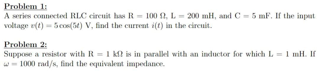
200 mH, and C = 5 mF. If the input Problem 1: 100 2, L = A series connected RLC circuit has R = voltage v(t) = 5 cos(5t) V, find the current i(t) in the circuit.


Q: (a) Determine the I-V characteristics equation at terminals a-b. Draw the approximate graph from the…
A: Given circuit is,Asked to determine the I V characteristics of the above circuit,Draw the simplest…
Q: Define what is used to determine the "steady state" of the charge/discharge phase of an RC Circuit.…
A: The given circuit isWe need to define the paramemter used to determine the "steady state" of the…
Q: What is the period of the wave form?
A: In this question, we need to determine the time period of the given waveform.
Q: DIGITAL SIGNAL PROCESSING ⑤THE INPUT fC+) AND THE IMPULSE ARE GIVEN BY RESPONSE n(+) OF AN LTI…
A:
Q: Show how to implement the sum-of-products circuit shown below using only NAND gates. Hint – use…
A: Please see the explanation Explanation:Step 1:
Q: wiring diagram for a single pole switch controlling the top half of a duplex receptacle that when…
A: The objective of this question is to provide a wiring diagram for a specific electrical setup. This…
Q: Implement the following Boolean function with only one multiplexer (8-to-1) and the minimal number…
A: In the given questions we need to implement the following Boolean function by using the 8×1 mux.
Q: Represent the electrical network by a state equation 12 292 x1(t) TH ΙΩ www www 1) € www 292 X2(1)…
A: The given circuit isWe need to determine the state space representation of the circuit.Note :…
Q: 1. For the circuit below: a) Determine the initial conditions i, (0+)and v. (0*). You must show the…
A: In d.c. analysis, under steady state condition, the inductor will behave as short circuit and…
Q: The circuit is configured as below and after waiting for a long time the switches are moved as…
A:
Q: find skin depth of a conductor with 10 mho/m at a frequency of 10mhz
A: The objective of this question is to calculate the skin depth of a conductor given its conductivity…
Q: a) I(O-) equals b) I at infinty time equals A c) The time constant t equals d) I at t=5ms equals A A…
A: In this question, we need to determine initial current in inductor, current at time t= ∞, time…
Q: We want to design a digital circuit that converts Gray code (ABC) to Binary code (xyz). Set up a…
A: See belowExplanation:
Q: Using Laplace transform, find io (t) for t>0. 4u(t)v+ 102 1F 1H 20 ww 102 e¹u(t)v io(t)
A: For the given circuit, it is asked to find the current io(t) for t>0 using Laplace transform
Q: Q3) Twenty voice signals are sampled uniformly and then time division multiplexed. The sampling…
A: The lowest sample rate needed to accurately represent a signal without aliasing is known as the…
Q: Write the mesh equations and solve for the mesh currents. Determine the voltage, V. XC R₂ HE w 202…
A: Mesh analysis is the combination of KVL and Ohm's law. KVL states that in any loop the algebraic sum…
Q: 1. The following are the input signals of a Balanced Modulator v1 = 8 sin[2π(200 x 10³)t] and V2 = 3…
A: (a) s(f) = -6j s(f - 200.2 * 103) + 6j s(f + 200.2 * 103) + 6j s(f - 199.8 * 103) -6j s(f + 199.8 *…
Q: Using g(p) = p³ + p² + 1, find the output codeword for [D]=[0011] and [D]=[0010]
A: Since you have posted multiple questions, we will provide the solution only to the first question as…
Q: 1- An 8-bit RTU microprocessor system with 6 channels can handle: A) 5 sensors B) 7 sensors C) 8…
A: In the given question we need to select the correct option among all the options.
Q: Problem 7-4: Design a cascading LC low-pass filter with maximally flat magnitude response. Use a…
A: cut off frequencyDesigned the cascading LC low pass filter.
Q: The current in an RLC circuit is described by d² + 10 + 25 i = 0 If (0) = 12 A and di(0)/dt = 0,…
A: It is asked to solve the given differential equation representing the current in RLC circuit
Q: Q) Joint pdf of (X, Y) is given by: f(x, y) = = 95 0 + y²) 0 ≤ x ≤ 1,0 ≤ y ≤ 1 Compute the…
A: The probability is determined by integrating with respect to x and y and substituting the limit of x…
Q: Determine the transfer function of the systems whose input-output behavior is shown below (It is not…
A: The input-output plots of two systems are given. It is asked to determine the transfer function of…
Q: Discuss the effect of the value of K on the system in terms of Percentage overshoot, peak time,…
A: It is asked to discuss the effects of the value of K on the system in terms of percentage overshoot,…
Q: The diagram shows an ideal (zero internal resistance) DC source connected to three identical…
A: Solution has been attached below.Explanation:
Q: Digital Signal Processing I Determine the period (c) FUIPAMENTAL FREQUENCY (w) AND CALCULATE FOURIER…
A: Since you have posted multiple questions, we will provide the solution only to the first question as…
Q: If Vs = 8 V, R1 = 13 Q2 and R2 = 62 2, what voltage would you expect to see displayed on a voltmeter…
A: Voltage divider rule, is a fundamental principle in electrical engineering used to determine the…
Q: H.W: Two point charges of 0.7mc and 4-9, Mc. are situated in free space at (2,3,6) and C0,0,0).…
A: The charge is and Calculate the force acting on the 0.7mC charge.The force is given by this formula
Q: A DC motor is fed with the armature voltage 430 V. At the current load, the speed is 180 rpm and the…
A: Given:Armature voltage (Va) = 430 VSpeed (n) = 180 rpmArmature current (Ia) = 29 AArmature…
Q: What is the region of operation of the FET circuit below? Assume Vτp = -0.4 V. 그 1V 푿 2V
A: From given circuit we write Drain voltage for cut off region For saturation region
Q: Determine the voltage across the inductor. write the same in sinusoidal form. 0163 R L 102 16 sim…
A: The given circuit isWe need to determine the voltage across the inductor, vL(t).
Q: Full-wave 50 Hz sinusoidal controlled rectifier circuit with a peak voltage value of 100 and a…
A: Given:Peak voltage value (Vm) = 100 VSource inductance (L) = 8 mHLoad current (Iload) = 8 AFiring…
Q: Write down the code table for the (7,4) multiplication cyclic code with generator polynomial g(p) =…
A: Given:Generator polynomial, we need to write: code table for (7, 4) multiplication cyclic code.
Q: 4 G(s) = = s3+5s2+8s+4 Convert the transfer function to state space in Jordan canonical
A: The transfer function of a system is given by⇒G(s)=4s3+5s2+8s+4 ;We need to convert the transfer…
Q: a. Find the expression for the electric field at P due to a point charge Q at (x1,y₁, Z₁) as shown…
A: Given that, The point charge is located at .Refer to the given figure is distance between and .
Q: Find the values to represent the Thevenin Equivalent Circuit 802 W 43 A 12 Ω VTH 10.8 Volts, RTH-4.8…
A: The circuit diagram,
Q: Q2. Select the correct answer of the following. 1. The full load voltage of transformer when…
A: In the given questions we need to select the correct option. The questions are related to the single…
Q: Example: consider the open-loop T.F GH(S)=1/S(S+2). Design PD- controller such that time constant…
A:
Q: 1. Hill Given the following circuit: R1 w 3Ω V1 12 V ·ទ 5Ω R2 w R3 4Ω Determine: a. R1, R2, R3, IR4,…
A: The circuit diagram,
Q: Using D flip-flops, design a logic circuit for the finite-state machine described by the state…
A: The state assigned table for a finite state machine is given byPresent stateNext…
Q: ▲i (mA) 20 20 05 -5 6 8 t (ms)
A: The given periodic signalHere time period T=8msnoe convert given signal in mathematical form
Q: For the following Ladder code, what are the elements needed to convert it into FBD? Stop_PB JE Start…
A: One of the primary programming languages used in PLCs is ladder logic, which derives its name from…
Q: 5. Show the connection of a three-stage amplifier with gains of +10, -18, and -27. Use a 270-k2…
A: In electronic circuits, amplifiers are essential components used to increase the strength of…
Q: The three loads in the circuit seen in (Figure 1) are S₁ =4+1 kVA, S2 5+ 12 kVA, and S₁ 10+50 kVA.…
A: The circuit diagram is shown below,
Q: 9. Find Io 12/0°V 102 www 2/0° A <10 1Ω M102 1Ω I
A: The given circuit isWe need to determine the current, Io.
Q: (II) Explain what happens if the topology is modified as shown in figure below. VREFO- ww Qz
A: According to questions we need explain about the given modified circuit.
Q: R1 520 2 ΚΩ Is S + Vs R2 1.5 ΚΩ R3 3 ΚΩ R4 3 ΚΩ www R7 4 ΚΩ www R5 2.4 ΚΩ R6 12 ΚΩ Figure 2. Circuit…
A:
Q: Given the waveform of the current in a 3H inductor as shown in figure, determine the inductor…
A: Given:Current waveform of 3 H inductor,we need to determine the inductor voltage and sketch it.
Q: A battery bank needs to store at least 2300 Wh of energy at 56 V outside where the ambient air…
A: According to the question,Battery capacity = 18 Ah at 10 VRequired battery bank =2300 Wh at 56 V
Q: Find Fourier coefficient
A: Given:To find:Fourier series of the given signal.

Step by step
Solved in 3 steps with 3 images

- For the circuit shown below, the initial conditions are zero, Idc is a current source continuous and switch S is open at t = 0.a)Determine the equivalent impedance to the right of points a and b of the circuit, Z(s).b)Obtain the voltage between points a and b of the circuit in the frequency domain, V(s). Employ the initial and final value properties and calculate the values of v(0) and v(∞).c)Find the expression for v(t). Check that the values of v(0) and v(∞) agree with those calculated in the previous item.d)Obtain currents i1(t) and i2(t).For the circuit shown below, the initial conditions are zero, Vdc is a voltage source continuous and switch S is closed at t = 0.a)Determine the equivalent impedance to the right of points a and b of the circuit, Z(s).b)Obtain the input current of the circuit in the frequency domain, I(s). employ the properties of the initial and final value and calculate the values of i(0) and i(∞).c)Find the expression for i(t). Check if the values of i(0) and i(∞) agree with those calculated in the previous item.d)Obtain voltages v1(t) and v2(t).characteristic impedance z0 = 50 ohms is a short-circuited coaxial (coaxial) cable with a length d = 0.3λ component is wanted to be made. Use Its frequency is f = 8 GHz. (a) Identify the component. (b) Find the impedance value of the component. (c) Find the parameter value of the component. lesson:electrical and electronical engineering
- An RLC circuit (has resistance and reactive elements) supplied by a 60Hz power source is found to have a lagging power factor (PF). What can you say about the relative contributions of the resistance (R), XL inductance, XC capacitance & resistance/reactance (ratio) utilized in this circuit at the 60Hz frequency? (min two statements – major reactive element & comparison to Resistive element)A 50ft transmission line is used for a microwave system. Aportion of the transmission line is found to have an inductanceof 0.5 mH, a capacitance of 1000 uF, 1000Ω resistance and 1uSconductance. Find the characteristic impedance of the trans lineassuming at Low frequency application.In an RLC series circuit, the voltage amplitude and frequency of the source are 100 V and 500 Hz, respectively, an R = 500Ω, L = 0.20 H, and C = 2.0μF. (a) What is the impedance of the circuit? (b) What is the amplitude of the current from the source? (c) If the emf of the source is given by v(t) = (100 V) sin 1000πt , how does the current vary with time? (d) Repeat the calculations with C changed to 0.20μF.
- A circuit is constructed with an AC generator, a resistor, capacitor and inductor as shown. The generator voltage varies in time as ε =Va - Vb = εmsinωt, where εm = 120 V and ω = 726 radians/second. The values for the remaining circuit components are: R = 62 Ω, L = 95.6 mH, and C = 13.8μF. 4) What is t1, the first time after t = 0 when the voltage across the inductor is zero? 6) What is VC = Vd - Va, the voltage across the capacitor, at time t = 0? Note that VC is a signed number.The inductance and capacity values used in a transmission path are 20 mH and 60 nF, respectively. Accordingly, find the significant impedance value that will eliminate the delay time per sector of this transmission path and the reflections at its output.Assume that the voltage drop across the resistor, ER, is 78 V, that the voltage drop across the inductor, EL, is 104 V, and the circuit has a total impedance, Z, of 20 . The frequency of the AC voltage is 60 Hz. ETITZ20VAPFER78VIRRPEL104VILXLVARsLL
- A series RLC circuit is constructed using component values R = 100 £2 and L = 1.5 mH along with a sinusoidal voltage source vs. If Qo= 7, determine (a) the magnitude of the impedance at 500 Mrad/s; (b) the current which flows in response to a voltage vs = 2.5 cos(425 × 10%t) V.For the circuit shown below, determine:a)The expression of the input current of the circuit in the time and frequency domain, respectively, i(t) and I(s).b)The circuit impedance, Z(s) = V(s)/I(s).c)The stress expression, v(t).d)The currents in the resistor, iR(t), and in the capacitor, iC(t).e)Repeat items c and d if v(0) = – 5 V.DISCRETE TIME GIVEN SYSTEM.Determine the poles and zeros of this system, and show how they relate to each other.The system is only marginally stable True False Find the frequency response of this system. ( NEED NEAT HANDWRITTEN SOLUTION ONLY OTHERWISE DOWNVOTE).