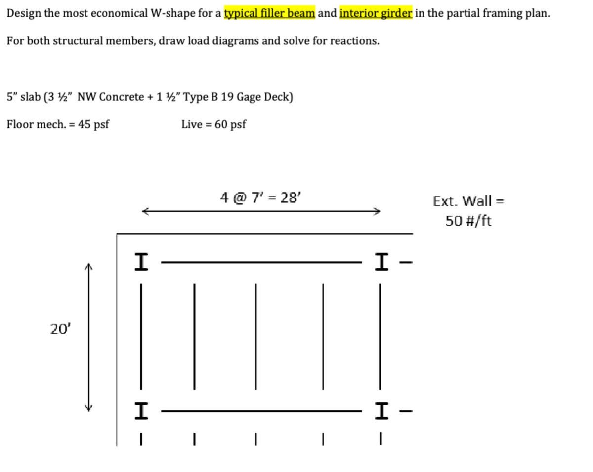
Design the most economical W-shape for a typical filler beam and interior girder in the partial framing plan. For both structural members, draw load diagrams and solve for reactions. 5" slab (3½" NW Concrete + 1 ½" Type B 19 Gage Deck) Floor mech. 45 psf = 20' H H | | Live = 60 psf 4 @ 7' = 28' Ext. Wall = 50 #/ft I - - H I - I


Q: A rigid bar is supported by a spring as shown in figure below: 50 kN/m B 5m 5m The deflection of…
A: For a rigid bar supported by a spring,To find the deflection of point C
Q: A retaining wall is 8 m high and having a vertical back. The soil behind the wall is having an angle…
A: A retaining wall is 8 meters high and has a vertical back.The soil behind the wall has an angle of…
Q: Find the coordinates of the centroid of the shape between the curve y = P+x² and the x- axis, for…
A: The objective of the question is to find the coordinates of the centroid of the shape formed between…
Q: 1. The figure below shows the flow net for seepage of water around a single row of sheet piles…
A:
Q: If a force, F= 20x (where x is in meter and F is in Newton) is acting on an object (at rest), then…
A: For given arrangement,A force, F =20x is acting on 5 kg block
Q: The rectangular steel frame shown is to support a footbridge in a chemical plant. The ends of the…
A:
Q: 2-35. Determine the reactions at the supports A and B. 500 lb/ft 30 ft 700 lb/ft 680 48 ft 48 ft…
A:
Q: Water at 20°C (p=998 kg/m³) is pumped out of a 10 cm in diameter pipe that con- sists of a 2 m long…
A:
Q: 200 mm X- 80 mm FIGURE P9-1 - X
A:
Q: Why assume that AB Azimuth is 30˚0'0"? Can't we find the azimuth of point F or E?
A: Why assume AB azimuth is 30 degree ?Can we find the azimuth of point F or E ?
Q: Find all the bearings and azimuths of the close traverse.
A: A closed traverse is given belowNeed to find all the bearings and azimuths of the close traverse
Q: There are three maior different types of precipitation that are classified by the producing…
A:
Q: embers Thursday Nov.24, 2020 3. Compute the design strength in tension, Pn, of an ASTM F1554 Gr. 36…
A: Compute the design strength in tension Pn, of an ASTM F1554 Gr. 36% in diameter THREADED rod.Your…
Q: 3. There is a vertical curve. The grade into the curve -3.6% and the grade out of the curve +4.4%.…
A:
Q: Three rods of equal length L and cross section area A, made of material Aluminum, rubber, steel and…
A:
Q: Problem 2 B a A d The 54-N force P is applied perpendicular to the portion BC. Given a = 35.1 deg…
A:
Q: 2- Determine the Elastic & Plastic moment capacity about the "y-y" axis of the steel section shown…
A: The yield strength is given as
Q: Please dont use Ai to answer the quastion. Its not a graded assignment
A: M_A = 360 k-ft M_B = -570 k-ft R_A = 53.125 k R_B = 9.375 kResults obtained from SAP 2000 with…
Q: SOLVE PART A For the beam shown, obtain: A). Applying the double integration method, the rotation in…
A:
Q: Consider a three hinged parabolic arch as shown in figure below: 50 KN 5m- B 9m 30 m What will be…
A:
Q: I will rate your answer, thanks
A: a)i. The soil will be clayey sand.ii. The soil will be hard and brittle.b)The soil is well graded…
Q: 60kN/m ↓ ↓ لا لا 4m 回 Т 60 kN.m 40 kN/m 6m C 105 kN ☑ ✓ ✓ 3m 2m Ima
A:
Q: Please answer the right answer and show all of your work please. Thank you for your help
A: d = 2.04mExplanation:
Q: Please answer the questions in the picture please
A: The total cost of the project is $ 3352.50Explanation:
Q: A W24 x 103 beam is subjected to the loads as shown. Find max. shear and max. moment. 6k 7k 8k 7k 6k…
A:
Q: The floor structural system shown in Fig 1 comprise W-section steel beams and girders supporting a…
A: SKETCH OF LOAD DISTRIBUTION IS SHOWN BELOW. I hope I answered your question :) Explanation:…
Q: A Masonary Dam &m high, 1.5m wide at the top and 5m wide at the Base retains water to a depth of 7.5…
A:
Q: 20mm Square plate is subjected normal stresses as illustrated. Modulus of Elasticity, E = 1081 MPa…
A:
Q: If: fc'=4ksi, and fyt=60ksi Determine: 1- Shear diagram. 2- Maximum shear at d from face of support.…
A:
Q: Determine the modulus of rigidity for a material that has a modulus of elasticity 75 GPa and…
A:
Q: Solut
A: Critical buckling load Pcr=122.89KipExplanation:Step 1: Critical buckling load Pcr=π2EI/Leff2For…
Q: F6-10. Draw the shear and moment diagrams for the simply supported beam. 6 kN/m m- 3 m- F6-10
A:
Q: need help 1)A W24 x 103 beam is subjected to the loads as shown. Find max. shear and max. moment.…
A: The objective of this question is to find the maximum shear and maximum moment in a beam subjected…
Q: A piece of (A =53 mm × B= 29 mm) material experiences a homogenous deformation. The deformed shape…
A:
Q: A 1.8 m high square concrete column with b = 220 mm (Ec ac = 9.9 × 10⁻⁶/° C) is reinforced with six…
A:
Q: 1. Prepare a set of profile leveling notes for the survey in Figure 1. In addition to computing all…
A: A profile leveling survey figure given belowNeed to findPrepare a set of profile leveling notes for…
Q: The floor structural system shown in Fig 1 comprise W-section steel beams and girders supporting a…
A: Slab thickness = 5 inLive load = 50 lb/ft2
Q: An earth embankment is to be compacted to a density of 19 kN/m³ at a moisture content of 14%. The…
A: The density of the compacted earth embankment is 19 kN/m³.The moisture content of the compacted…
Q: L. A diver stands on the end of a diving board. If the diver's mass is 70 kg, determine the shear…
A:
Q: As shown in the figure below, a horizontal alignment consists of two tangent lines smoothened by a…
A: Given:Station PC is at 20+30.00Station PT is at 24+00.00Super elevation = 210 ft
Q: A fixed beam is loaded as shown below: 20 kN/m 30 kN/m B 10 m What will be value of vertical…
A: For a fixed beam with loading as shown below,To find the vertical reaction at A
Q: F6-12. Draw the shear and moment diagrams for the simply supported beam. 10 kN/m 3m- -3 m- 10 kN/m B
A: The sum of force in the y directiontaking moment about Alets RA is
Q: 2- With both ASD and LRFD methods to check the adequacy the W10x33 shape as a column subjected to…
A: W10x33DL = 100 kipsLL = 70 kips
Q: 400 lb E R₁ 3 R₂ 20 in 30 in 600 lb 41009 -400 1 1 300 lb 11 200 lb 300 lb 80 lb 3. Find the initial…
A:
Q: Which of the following statements are correct (select all that apply) ? Group of answer choices…
A: The objective of the question is to identify the correct statements among the given options related…
Q: An article gave a scatter plot along with the least squares line of x = rainfall volume (m³) and y =…
A: Calculate :(a) Does a scatter plot of the data support the use of the simple linear regression…
Q: Determine the distance of O (shear center) to the center of mass A in base unit with 1 digits after…
A: The objective of the problem is to determine the distance shear center, to the center of mass.Given,
Q: EX/ Analyze the truss shown. EA is constant for all members 2 50/N looku B +2mflfll 2 wh
A: Analyze the truss shown. EA is constant for all members
Q: Determine the Formula of the fixed end moments of the beams given below. 1) USE DOUBLE-INTEGRATION…
A: As per Bartleby's guide lines only first four sub- questions will be answered. Please upload the…
Q: The measured photo coordinates of images a and b of two ground points A and B are x =+ 45.35 mm; y =…
A:
Design the most economical W-shape for a typical filler beam and interior girder in the partial framing plan.
For both structural members, draw load diagrams and solve for reactions.
thank you for the help

Step by step
Solved in 1 steps

- Simply Supported Beam ABCDE below carries multiple loads as shown. A built-upsection made from a T-Section and a Channel (C-Section) fastened together by 16mm∅ bolts,equally spaced from the center of the section, with shearing capacity τ=100 MPa, for bearing σb= 220 MPa for rivets in single shear and σb = 280 MPa for rivets in double shear. E=200GPa forall materials. Determine the maximum flexural stress at 1 m from the support at D to E in MPa.The overhanging beam shown supports the given ultimate load Wu= 5okN/m. The section is 300mm by 500mm rectangular beam having f'c=35MPa, fy=420 MPa, stirrups diameter = 10mm and concrete cover 40mm. a.) the area of steel reinforcement corresponding to rho max in mm2.b.) the location of the point of zero shear in the beam measured from the left support B in mm.c.) Calculate the maximum positive moment in the beam in kN.m.d.) Calculate the required reinforcement Asreqd corresponding to the maximum positive moment in mm2.e.) Calculate the depth of the compression block of the final positive moment section in mm.f.) Calculate the depth of the neutral axis of the final positive moment section in mm.g.) What is the ultimate moment capacity of the final positive moment section in kN.m.h.) Calculate the additional positive moment that can be imposed to the beam without exceeding the moment capacity of the final positive moment section in kN.m.The floor system used in a school classroom consists of a 4-in. reinforced stone concrete slab. Sketch the loading that acts along the joist BF and side girder ABCDE. Set a = 7.5 ft, b = 20 ft. Hint: See Tables 1.2 and 1.4.
- Simply Supported Beam ABCDE below carries multiple loads as shown. A built-upsection made from a T-Section and a Channel (C-Section) fastened together by 16mm∅ bolts,equally spaced from the center of the section, with shearing capacity τ=100 MPa, for bearing σb= 220 MPa for rivets in single shear and σb = 280 MPa for rivets in double shear. E=200GPa forall materials. a. Determine the location of Neutral Axis, in mm, from the top of the section.b. Determine the location of the centroid, in mm, from the left of the section.Simply Supported Beam ABCDE below carries multiple loads as shown. A built-upsection made from a T-Section and a Channel (C-Section) fastened together by 16mm∅ bolts,equally spaced from the center of the section, with shearing capacity τ=100 MPa, for bearing σb= 220 MPa for rivets in single shear and σb = 280 MPa for rivets in double shear. E=200GPa forall materials. Determine the maximum positive bending moment in the beam in kN-m.A W6 X 116 section is to serve as a purlin between roof trusses which is 7.2 meters on center. The roof is assumed to support a dead load of 960 N/m^2 including its own weight and a live load of 894.154 N/m^2. The slope roof truss is 1 vertical to 2 horizontal and the purlins are to be spaced at 1.8m on centers. Using A36steel with Fy=248 MPa. Assume all loads will act at the center of gravity of the section. Sag rods are to be placed at the middle thirds between trusses. Properties of W 6 x 116 A=3058 mm2 d = 159.51 mm bf = 102.36 mm tf = 10.29 mm tw = 6.60 mm Sx = 167 x 10^3 mm3 Sy = 36 x 10^3 mm3 Using DL+LL only a. Determine the bending stress along the Normal axis bending in MPa b. Determine the bending stress along the Tangential axis bending in MPa c. Determine the DCR if the capacity Fbx = 0.66Fy and Fby = 0.75Fy really need the answer
- Simply Supported Beam ABCDE below carries multiple loads as shown. A built-upsection made from a T-Section and a Channel (C-Section) fastened together by 16mm∅ bolts,equally spaced from the center of the section, with shearing capacity τ=100 MPa, for bearing σb= 220 MPa for rivets in single shear and σb = 280 MPa for rivets in double shear. E=200GPa forall materials. Determine the location of Neutral Axis, in mm, from the top of the section.Compute the internal force of member CD & EFPROBLEM: Light grade steel channel was used as purlin of the truss. The top chord of the truss is inclined 1V:3H and the distance between the trusses is 5m. The purlin weighs 100n/m and spaced at 1m apart. The roof carries superimposed dead load of 1000 Pa (including its weight) and the ceiling carries a load of 1200 Pa. Roof live load is assumed to be 1500 Pa. The roof is part of the building located at a place where the design wind speed is 240 kph. Assume the unit weight of air to be 12 N/m3. The windward coefficient is 0.20 and the leeward coefficient is 0.70. For this problem, assume that the allowable bending stress of beam is 60% and 75% of its yield strength in the strong and weak axis respectively. Assume all loads passes through the centroid of the section. Properties of C 250x85 ; Sx= 122 x103 mm3 ; Sy= 49 x103 mm3; Fy=300 MPa; Fbx (Allow. Bending Stress)=0.6Fy;Fby (Allow. Bending Stress)=0.75Fy What is the ratio of the actual to allowable bending stress for load…
- Simply Supported Beam ABCDE below carries multiple loads as shown. A built-upsection made from a T-Section and a Channel (C-Section) fastened together by 16mm∅ bolts,equally spaced from the center of the section, with shearing capacity τ=100 MPa, for bearing σb= 220 MPa for rivets in single shear and σb = 280 MPa for rivets in double shear. E=200GPa forall materials. 1. Determine the maximum positive bending moment in the beam in kN-m.2. Determine the maximum shear in kN.3. Determine the location of Neutral Axis, in mm, from the top of the section.Simply Supported Beam ABCDE below carries multiple loads as shown. A built-upsection made from a T-Section and a Channel (C-Section) fastened together by 16mm∅ bolts,equally spaced from the center of the section, with shearing capacity τ=100 MPa, for bearing σb= 220 MPa for rivets in single shear and σb = 280 MPa for rivets in double shear. E=200GPa forall materials. Determine the maximum flexural stress experienced by the beam in MPa.A short rectangular column 300 mm on one side and 400 mm on the other side. It is reinforced with 8-20-mm-diameter (28) longhitudinal bars equally distributed to the shorte sides of the column. Use f'c = 21 MPa and fy = 415 MPa. Calculate the required spacing of 10-mm-diameter ties, s (mm). Calculate the nominal axial strength of the column, Pn (kN). Calculate the maximum ultimate axial load the column can carry, Pu (kN)