
Engineering Mechanics: Statics & Dynamics (14th Edition)
14th Edition
ISBN: 9780133915426
Author: Russell C. Hibbeler
Publisher: PEARSON
expand_more
expand_more
format_list_bulleted
Videos
Textbook Question
Chapter 6.3, Problem 1PP
In each case, calculate the support reactions and then draw the free-body diagrams of joints A, B, and C of the truss.
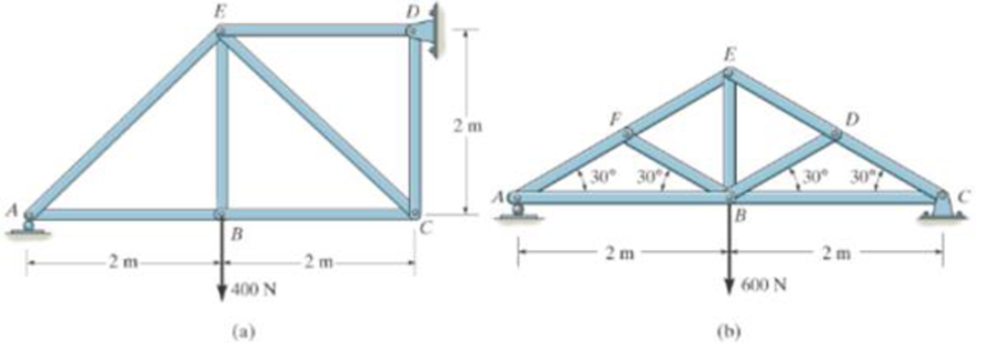
Prob. P6-1
Expert Solution & Answer

Learn your wayIncludes step-by-step video

schedule08:29
Students have asked these similar questions
Problem 6.
•5-5. Draw the free-body diagram of the truss that is
supported by the cable AB and pin C.
B
30°
2 m
3 kN
4 kN
2 m
2 m
2 m
Prob. 5-5
tension or compression. Approximate each joint as a pin.
6-23. The Fink truss supports the loads shown. Determine
the force in each member and state if the members are in
or
500 lb
1000 lb
2.5 ft
1000 lb
2.5 ft
ID
1000 lb
30°
2.5 ft
500 lb 2.5 ft
30°
A
H
Prob. 6-23
Use the method of joints to determine the force in each.
member of the truss shown in the following problems. State
whether each member is in tension or compression.
Determine the forces in members AD, CD, and DE
of the truss shown in Fig. P7-15.
3000 Ib
2000 Ib
6 ft
D.
6 t
B
Chapter 6 Solutions
Engineering Mechanics: Statics & Dynamics (14th Edition)
Ch. 6.3 - In each case, calculate the support reactions and...Ch. 6.3 - Identify the zero-force members in each truss....Ch. 6.3 - Determine the force in each member of the truss....Ch. 6.3 - Determine the force in each member of the truss....Ch. 6.3 - Determine the force in each member of the truss....Ch. 6.3 - Determine the greatest load P that can be applied...Ch. 6.3 - Identify the zero-force members in the truss....Ch. 6.3 - Determine the force in each member of the truss....Ch. 6.3 - Determine the force in each member of the truss...Ch. 6.3 - Determine the force in each member of the truss...
Ch. 6.3 - Determine the force in each member of the truss....Ch. 6.3 - Determine the force in each member of the truss...Ch. 6.3 - Prob. 5PCh. 6.3 - Determine the force in each member of the truss,...Ch. 6.3 - Determine the force in each member of the truss...Ch. 6.3 - Determine the force in each member of the truss...Ch. 6.3 - Prob. 9PCh. 6.3 - Determine the force in each member of the truss...Ch. 6.3 - Determine the force in each member of the Pratt...Ch. 6.3 - Determine the force in each member of the truss...Ch. 6.3 - Determine the force in each member of the truss in...Ch. 6.3 - Members AB and BC can each support a maximum...Ch. 6.3 - Members AB and BC can each support a maximum...Ch. 6.3 - Determine the force in each member of the truss....Ch. 6.3 - If the maximum force that any member can support...Ch. 6.3 - Determine the force in each member of the truss...Ch. 6.3 - Determine the force in each member of the truss...Ch. 6.3 - Prob. 20PCh. 6.3 - Determine the force in each member of the truss...Ch. 6.3 - Determine the force in each member of the double...Ch. 6.3 - Prob. 23PCh. 6.3 - The maximum allowable tensile force in the members...Ch. 6.3 - Determine the force in each member of the truss in...Ch. 6.3 - The maximum allowable tensile force in the members...Ch. 6.4 - Determine the force in members BC, CF, and FE....Ch. 6.4 - Determine the force in members LK, KC, and CD of...Ch. 6.4 - Determine the force in members KJ, KD, and CD of...Ch. 6.4 - Determine the force in members EF, CF, and BC of...Ch. 6.4 - Determine the force in members GF, GD, and CD of...Ch. 6.4 - Determine the force in members DC, HI, and JI of...Ch. 6.4 - Determine the force in members DC, HC, and HI of...Ch. 6.4 - Determine the force in members ED, EH, and GH of...Ch. 6.4 - Determine the force in members HG, HE and DE of...Ch. 6.4 - Determine the force in members CD, HI, and CH of...Ch. 6.4 - Prob. 31PCh. 6.4 - Prob. 32PCh. 6.4 - Prob. 33PCh. 6.4 - Prob. 34PCh. 6.4 - Determine the force in members EF, CF, and BC, and...Ch. 6.4 - Determine the force in members AF, BF, and BC, and...Ch. 6.4 - Prob. 39PCh. 6.4 - Determine the force in members CD, CF, and CG and...Ch. 6.4 - Determine the force developed in members FE, EB,...Ch. 6.4 - Determine the force in members BC, HC, and HG....Ch. 6.4 - Determine the force in members CD, CJ, GJ, and CG...Ch. 6.4 - Determine the force in members BE, EF, and CB, and...Ch. 6.4 - Prob. 45PCh. 6.4 - Determine the force in members BC, CH, GH, and CG...Ch. 6.4 - Determine the force in members CD, CJ, and KJ and...Ch. 6.4 - Prob. 48PCh. 6.4 - Determine the force in members HI, FI, and EF of...Ch. 6.6 - In each case, identify any two-force members, and...Ch. 6.6 - Determine the force P needed to hold the 60-lb...Ch. 6.6 - Determine the horizontal and vertical components...Ch. 6.6 - If a 100-N force is applied to the handles of the...Ch. 6.6 - Determine the horizontal and vertical components...Ch. 6.6 - Determine the normal force that the 100-lb plate A...Ch. 6.6 - Determine the force P needed to lift the load....Ch. 6.6 - Prob. 19FPCh. 6.6 - Prob. 20FPCh. 6.6 - Determine the components of reaction at A and C....Ch. 6.6 - Determine the components of reaction at C. Prob....Ch. 6.6 - Determine the components of reaction at E. Prob....Ch. 6.6 - Determine the components of reaction at D and the...Ch. 6.6 - Determine the force P required to hold the 100-lb...Ch. 6.6 - In each case, determine the force P required to...Ch. 6.6 - Determine the force P required to hold the 50-kg...Ch. 6.6 - Determine the force P required to hold the 150-kg...Ch. 6.6 - Determine the horizontal and vertical components...Ch. 6.6 - Determine the horizontal and vertical components...Ch. 6.6 - Determine the force that the smooth rotor C exerts...Ch. 6.6 - The bridge frame consists of three segments which...Ch. 6.6 - Determine the reactions at supports A and B. Prob....Ch. 6.6 - Determine the horizontal and vertical components...Ch. 6.6 - Determine the reactions at the supports A, C, and...Ch. 6.6 - Determine the resultant force at pins A, B, and C...Ch. 6.6 - Determine the reactions at the supports at A, E,...Ch. 6.6 - The wall crane supports a load of 700 lb....Ch. 6.6 - The wall crane supports a load of 700 lb....Ch. 6.6 - Determine the horizontal and vertical components...Ch. 6.6 - The two-member structure is connected at C by a...Ch. 6.6 - The compound beam is pin supported at B and...Ch. 6.6 - When a force of 2 lb is applied to the handles of...Ch. 6.6 - The toggle clamp is subjected to a force F at the...Ch. 6.6 - The hoist supports the 125-kg engine. Determine...Ch. 6.6 - A 5-lb force is applied to the handles of the vise...Ch. 6.6 - Determine the force in members FD and DB of the...Ch. 6.6 - Determine the force that the smooth 20-kg cylinder...Ch. 6.6 - Prob. 85PCh. 6.6 - The pumping unit is used to recover oil. When the...Ch. 6.6 - Determine the force that the jaws J of the metal...Ch. 6.6 - Prob. 88PCh. 6.6 - Determine the horizontal and vertical components...Ch. 6.6 - The pipe cutter is clamped around the pipe P. If...Ch. 6.6 - Determine the force created in tire hydraulic...Ch. 6.6 - Determine the horizontal and vertical components...Ch. 6.6 - The constant moment of 50 N m is applied to the...Ch. 6.6 - Five coins are stacked in the smooth plastic...Ch. 6.6 - The nail cutter consists of the handle and the two...Ch. 6.6 - A man having a weight of 175 lb attempts to hold...Ch. 6.6 - Prob. 97PCh. 6.6 - The two member frame is pin connected at E. The...Ch. 6.6 - If the 300 kg drum has a center of mass at point...Ch. 6.6 - Operation of exhaust and intake valves in an...Ch. 6.6 - If a clamping force of 300 N is required at A,...Ch. 6.6 - If a force of F = 350 N is applied to the handle...Ch. 6.6 - Determine the horizontal and vertical components...Ch. 6.6 - The hydraulic crane is used to lift the 1400-lb...Ch. 6.6 - Determine force P on the cable if the spring is...Ch. 6.6 - Prob. 106PCh. 6.6 - If a force of F = 50 lb is applied to the pads at...Ch. 6.6 - The skid-steer loader has a mass of 1.18 Mg, and...Ch. 6.6 - Determine the force P on the cable if the spring...Ch. 6.6 - The spring has an unstretched length of 0.3 m....Ch. 6.6 - The spring has an unstretched length of 0.3 m....Ch. 6.6 - The piston C moves vertically between the two...Ch. 6.6 - Prob. 113PCh. 6.6 - The platform scale consists of a combination of...Ch. 6.6 - The three pin-connected members shown in the top...Ch. 6.6 - Determine the force in each member of the truss...Ch. 6.6 - Determine the force in each member of the truss...Ch. 6.6 - Determine the force in member GJ and GC of the...Ch. 6.6 - Determine the force in members GF, FB, and BC of...Ch. 6.6 - Determine the horizontal and vertical components...Ch. 6.6 - Determine the horizontal and vertical components...Ch. 6.6 - Determine the resultant forces at pins B and C on...
Additional Engineering Textbook Solutions
Find more solutions based on key concepts
F43. Determine the moment of the force about point O.
Engineering Mechanics: Statics
Determine the reactions at the supports A and B. El is constant.
Mechanics of Materials (10th Edition)
Figure 8.12shows a portion of a fire protection system in which a pump draws water at 60 F from a reservoir and...
Applied Fluid Mechanics (7th Edition)
Determine the force in members BE, EF, and CB, and state if the members are in tension or compression. Probs. 6...
INTERNATIONAL EDITION---Engineering Mechanics: Statics, 14th edition (SI unit)
ICA 17-24
The decay of a radioactive isotope can be theoretically modeled with the following equation, where C0...
Thinking Like an Engineer: An Active Learning Approach (4th Edition)
If it is released from rest when = 0. determine the magnitude of the reactive force exerted on it by pin B whe...
Engineering Mechanics: Dynamics (14th Edition)
Knowledge Booster


Learn more about
Need a deep-dive on the concept behind this application? Look no further. Learn more about this topic, mechanical-engineering and related others by exploring similar questions and additional content below.Similar questions
- 7-22 Determine the forces in members CD, DI, and HI of the truss shown in Fig. 18 kN 10 kN 14 kN E 3 m B H 3 m A 3 m 3 m 3 m -3 m -3 m 3 m-arrow_forward6-11. Determine the force in each member of the Pratt truss, and state if the members are in tension or compression. J 2 m 2 m L H 2 m C E F -2 m--2 m--2 m--2 m---2 m--2 m- 10 kN 10 kN 20 kN Prob. 6-11arrow_forwardP5-3. then draw the free-body diagrams of each member of the identify any two-force members, and frame. 400 N/m -3 m 1marrow_forward
- The 300 kg uniform I-beam supports the 120 kg load. What are the reactions at the supports A and B? 5.6 m - 2.4 m B A 120 kgarrow_forward6-9. Determine the force in each member of the truss state if the members are in tension or compression. P₁ = 800 lb, P₂ = 600 lb. bers 10 ft - A P₂ 30⁰ B 60° 10 ft- P₁ с F D 60° Prob. 6-9 30° -10 ft-arrow_forwardThe multispan girder has two shear plate connections that act as hinges at C and D. The midspan girder CD is simply supported on the cantilevered ends of the left and right girders. Determine the forces in the hinges and the reactions at supports A, B, E, and F. Also draw the shear and moment diagram.arrow_forward
- 6-30. Determine the force in members CD, HI, and CH of the truss, and state if the members are in tension or compression. -3 ft--3 ft--3 a--3a--3 - 1500 Ib 1500 lb 1500 Ib 1500 Ib 1500 lb Probs. 6–29/30arrow_forward6-40. The compound beam is fixed supported at C and supported by rockers at A and B. If there are hinges (pins) at D and E, determine the components of reaction at the supports. Neglect the thickness of the beam. 900 lb 400 lb A 0 2 ft 300 lb B FRESSPOR -6 ft4 ft 4 ft D 4 ft- 2 ft Prob. 6-40 E 650 lb 13/12 2 ft C -8 ft- 4arrow_forward6-44 Determine the force exerted by the cable at B and the reaction at support A of the curved bar shown in Fig. 850 N Cable 220 B C 40° A 300 mm 275 mmarrow_forward
- 6-51. Determine the force in each member of the space truss and state if the members are in tension or compression. The truss is supported by short links at A, B, and C. 4 ft. X 2 ft D Z 8 ft B Prob. 6-51 {500j} lb 3 ft 2 ft yarrow_forwardThe frame shown is supported by a pin at A and a fixed support at D. There are internal hinges/pins at and C. Assume P = 5 kips and w = 1 kip/ft. Determine all of the external support reactions. Clearly st true direction of each reaction. W 10 ft B -8 ft- D 2 ft 4 ft -Parrow_forward6-46. Determine the force developed in members BC and CH of the roof truss and state if the members are in tension or compression. Determine the force in members CD and GF of the truss and state if the members are in tension or compression. Also indicate all zero-force members. 2 kN 1.5 m 0.8 m B A |H G |F E ▼1.5 kN -2 m - -2 m - Probs. 6–46/47 Fec = 3.25 kN (C) Fen= 1.92 kN (T) Answers:arrow_forward
arrow_back_ios
SEE MORE QUESTIONS
arrow_forward_ios
Recommended textbooks for you
 Elements Of ElectromagneticsMechanical EngineeringISBN:9780190698614Author:Sadiku, Matthew N. O.Publisher:Oxford University Press
 Mechanics of Materials (10th Edition)Mechanical EngineeringISBN:9780134319650Author:Russell C. HibbelerPublisher:PEARSON
 Thermodynamics: An Engineering ApproachMechanical EngineeringISBN:9781259822674Author:Yunus A. Cengel Dr., Michael A. BolesPublisher:McGraw-Hill Education
 Control Systems EngineeringMechanical EngineeringISBN:9781118170519Author:Norman S. NisePublisher:WILEY
 Mechanics of Materials (MindTap Course List)Mechanical EngineeringISBN:9781337093347Author:Barry J. Goodno, James M. GerePublisher:Cengage Learning
 Engineering Mechanics: StaticsMechanical EngineeringISBN:9781118807330Author:James L. Meriam, L. G. Kraige, J. N. BoltonPublisher:WILEY
Elements Of Electromagnetics
Mechanical Engineering
ISBN:9780190698614
Author:Sadiku, Matthew N. O.
Publisher:Oxford University Press
Mechanics of Materials (10th Edition)
Mechanical Engineering
ISBN:9780134319650
Author:Russell C. Hibbeler
Publisher:PEARSON
Thermodynamics: An Engineering Approach
Mechanical Engineering
ISBN:9781259822674
Author:Yunus A. Cengel Dr., Michael A. Boles
Publisher:McGraw-Hill Education
Control Systems Engineering
Mechanical Engineering
ISBN:9781118170519
Author:Norman S. Nise
Publisher:WILEY
Mechanics of Materials (MindTap Course List)
Mechanical Engineering
ISBN:9781337093347
Author:Barry J. Goodno, James M. Gere
Publisher:Cengage Learning
Engineering Mechanics: Statics
Mechanical Engineering
ISBN:9781118807330
Author:James L. Meriam, L. G. Kraige, J. N. Bolton
Publisher:WILEY
Physics 33 - Fluid Statics (1 of 10) Pressure in a Fluid; Author: Michel van Biezen;https://www.youtube.com/watch?v=mzjlAla3H1Q;License: Standard YouTube License, CC-BY