00 Unit 23 Instrumentation and Control Drawings 445 3 EXHAUST MAN MAN T AIR 9 L (12) 2-WAY PUSH-BUTTON VALVE CLIPPARD MJV-2 3) TIMAC AIR TIME DELAY VALVE TIMING RANGE .2-20 SECONDS MAC VAKVES INC. MODEL 71A-2-2 4) AIR CYLINDER AIRMATIC VALVE INC. 5) 4-WAY 5-PORT SPRING RETURN VALVE MILLER FLUID POWER CO. MODEL 504, 1/4 NPT LUB. (67 EXHAUST CONTROL AIRMATIC VALVE INC. OR VERSA PRODUCTS CO. 6 8) SHUT OFF VALVE 9 FILTER-REGULATOR-LUBRICATOR COMBINATION WITH PRESSURE GAUGE. NORGREN FILT. UNIDYNAMICS PHOENIX PHOENIX, ARIZONA A DIVISION OF UMC INDUSTRIES, INC. TOOL NAME PNEUMATIC CIRCUIT FOR DEAD WEIGHT PRESS CODE IDENT NO. DWG (TOOL) NO. 3ZIS B 12079 20-837 Print supplied by Unidynar PH 23-1. Pneumatic Circuit for Dead Weight Press. Copyright Goodheart-Willcox Co., Inc. Refer to print PR 23-1. The sequence of operations for this print is given below. Answer the questions following the sequence of operations Sequence of operations 1. The operator actuates the two push-button valves (1) and (2) until the weight starts to descend. 2. Air passes through valves (1) and (2) to the time delay valve (3) and the pilot of valve (5). 3. The four-way valve (5) is shifted, venting the head end of cylinder (4) and pressurizing the rod end. 4 The weight of the ram descends The speed of descent is controlled by the exhaust control (7). 6. The time delay valve (3) continues to time until the preset interval has passed. 7. The time delay valve (3) vents air pressure from the line between valve (2) and the pilot of valve (5) 8. With the pilot vented, the spring return of valve (5) shifts the valve to its normal position. The rod end of cylinder (4) is vented and the head end is pressurized. 10. The weight ascends. 11. The speed of ascent is controlled by the exhaust control (6). Questions 8. What causes cylinder (4) to reverse? lonexe inh 9. What does the center line around valve (3) indicate? What component(s) are included? 10. Why is it not necessary to hold valves (1) and (2) down during the entire sequence?
00 Unit 23 Instrumentation and Control Drawings 445 3 EXHAUST MAN MAN T AIR 9 L (12) 2-WAY PUSH-BUTTON VALVE CLIPPARD MJV-2 3) TIMAC AIR TIME DELAY VALVE TIMING RANGE .2-20 SECONDS MAC VAKVES INC. MODEL 71A-2-2 4) AIR CYLINDER AIRMATIC VALVE INC. 5) 4-WAY 5-PORT SPRING RETURN VALVE MILLER FLUID POWER CO. MODEL 504, 1/4 NPT LUB. (67 EXHAUST CONTROL AIRMATIC VALVE INC. OR VERSA PRODUCTS CO. 6 8) SHUT OFF VALVE 9 FILTER-REGULATOR-LUBRICATOR COMBINATION WITH PRESSURE GAUGE. NORGREN FILT. UNIDYNAMICS PHOENIX PHOENIX, ARIZONA A DIVISION OF UMC INDUSTRIES, INC. TOOL NAME PNEUMATIC CIRCUIT FOR DEAD WEIGHT PRESS CODE IDENT NO. DWG (TOOL) NO. 3ZIS B 12079 20-837 Print supplied by Unidynar PH 23-1. Pneumatic Circuit for Dead Weight Press. Copyright Goodheart-Willcox Co., Inc. Refer to print PR 23-1. The sequence of operations for this print is given below. Answer the questions following the sequence of operations Sequence of operations 1. The operator actuates the two push-button valves (1) and (2) until the weight starts to descend. 2. Air passes through valves (1) and (2) to the time delay valve (3) and the pilot of valve (5). 3. The four-way valve (5) is shifted, venting the head end of cylinder (4) and pressurizing the rod end. 4 The weight of the ram descends The speed of descent is controlled by the exhaust control (7). 6. The time delay valve (3) continues to time until the preset interval has passed. 7. The time delay valve (3) vents air pressure from the line between valve (2) and the pilot of valve (5) 8. With the pilot vented, the spring return of valve (5) shifts the valve to its normal position. The rod end of cylinder (4) is vented and the head end is pressurized. 10. The weight ascends. 11. The speed of ascent is controlled by the exhaust control (6). Questions 8. What causes cylinder (4) to reverse? lonexe inh 9. What does the center line around valve (3) indicate? What component(s) are included? 10. Why is it not necessary to hold valves (1) and (2) down during the entire sequence?

Automotive Technology: A Systems Approach (MindTap Course List)
6th Edition
ISBN:9781133612315
Author:Jack Erjavec, Rob Thompson
Publisher:Jack Erjavec, Rob Thompson
Chapter26: Ignition Systems
Section: Chapter Questions
Problem 8ASRQ: While discussing El systems: Technician A says that when the engine is being cranked, the PCM relies...

Related questions

Question
100%
I need parts 8, 9, and 10 answered pertaining to the print provided and the set of sequence operations.
Note: If you can not answer all 3 parts, leave it for another tutor please, thank you.
Transcribed Image Text:00
Unit 23
Instrumentation and Control Drawings
445
3
EXHAUST
MAN
MAN
T
AIR
9
L
(12) 2-WAY PUSH-BUTTON VALVE
CLIPPARD MJV-2
3) TIMAC AIR TIME DELAY VALVE
TIMING RANGE .2-20 SECONDS
MAC VAKVES INC.
MODEL 71A-2-2
4) AIR CYLINDER
AIRMATIC VALVE INC.
5) 4-WAY 5-PORT SPRING
RETURN VALVE
MILLER FLUID POWER CO.
MODEL 504, 1/4 NPT
LUB.
(67 EXHAUST CONTROL
AIRMATIC VALVE INC. OR
VERSA PRODUCTS CO.
6
8) SHUT OFF VALVE
9 FILTER-REGULATOR-LUBRICATOR
COMBINATION WITH PRESSURE
GAUGE.
NORGREN
FILT.
UNIDYNAMICS
PHOENIX
PHOENIX,
ARIZONA
A DIVISION OF UMC INDUSTRIES, INC.
TOOL NAME
PNEUMATIC CIRCUIT FOR
DEAD WEIGHT PRESS
CODE IDENT NO. DWG (TOOL) NO.
3ZIS
B 12079
20-837
Print supplied by Unidynar
PH 23-1. Pneumatic Circuit for Dead Weight Press.
Copyright Goodheart-Willcox Co., Inc.
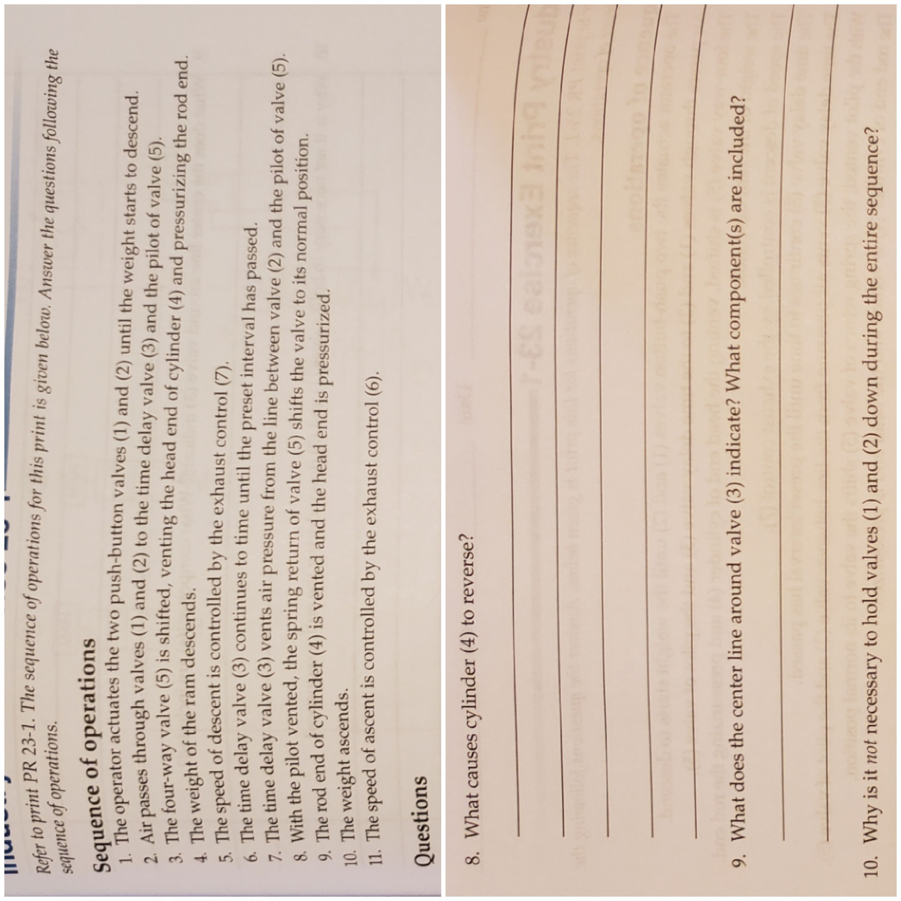
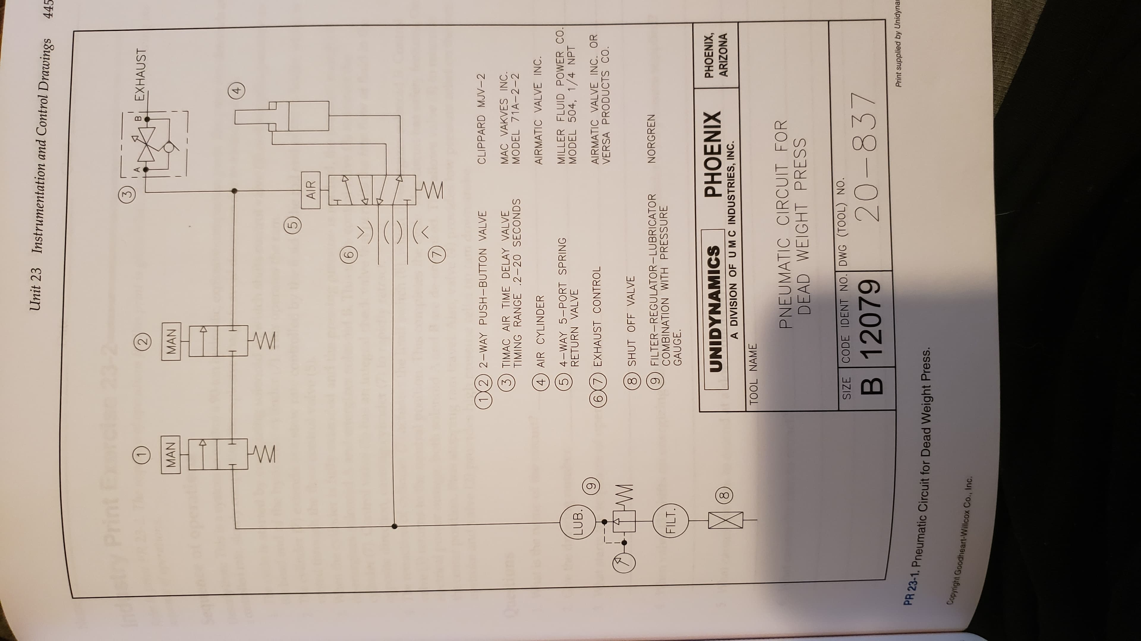
Transcribed Image Text:Refer to print PR 23-1. The sequence of operations for this print is given below. Answer the questions following the
sequence of operations
Sequence of operations
1. The operator actuates the two push-button valves (1) and (2) until the weight starts to descend.
2. Air passes through valves (1) and (2) to the time delay valve (3) and the pilot of valve (5).
3. The four-way valve (5) is shifted, venting the head end of cylinder (4) and pressurizing the rod end.
4 The weight of the ram descends
The speed of descent is controlled by the exhaust control (7).
6. The time delay valve (3) continues to time until the preset interval has passed.
7. The time delay valve (3) vents air pressure from the line between valve (2) and the pilot of valve (5)
8. With the pilot vented, the spring return of valve (5) shifts the valve to its normal position.
The rod end of cylinder (4) is vented and the head end is pressurized.
10. The weight ascends.
11. The speed of ascent is controlled by the exhaust control (6).
Questions
8. What causes cylinder (4) to reverse?
lonexe inh
9. What does the center line around valve (3) indicate? What component(s) are included?
10. Why is it not necessary to hold valves (1) and (2) down during the entire sequence?
Expert Solution
This question has been solved!
Explore an expertly crafted, step-by-step solution for a thorough understanding of key concepts.

This is a popular solution!

Trending now
This is a popular solution!

Step by step
Solved in 3 steps with 1 images

Knowledge Booster


Learn more about
Need a deep-dive on the concept behind this application? Look no further. Learn more about this topic, mechanical-engineering and related others by exploring similar questions and additional content below.Recommended textbooks for you
Automotive Technology: A Systems Approach (MindTa…
Mechanical Engineering
ISBN:
9781133612315
Author:
Jack Erjavec, Rob Thompson
Publisher:
Cengage Learning

Refrigeration and Air Conditioning Technology (Mi…
Mechanical Engineering
ISBN:
9781305578296
Author:
John Tomczyk, Eugene Silberstein, Bill Whitman, Bill Johnson
Publisher:
Cengage Learning
Automotive Technology: A Systems Approach (MindTa…
Mechanical Engineering
ISBN:
9781133612315
Author:
Jack Erjavec, Rob Thompson
Publisher:
Cengage Learning
Refrigeration and Air Conditioning Technology (Mi…
Mechanical Engineering
ISBN:
9781305578296
Author:
John Tomczyk, Eugene Silberstein, Bill Whitman, Bill Johnson
Publisher:
Cengage Learning