01 1- Determine the output voltage waveform for the Schmitt trigger shown in relation to a 1 kHz sine wave with peak values of ;10 V. +11.2 V Rbias 40 k Vin OTA -Vout - 11.2 V 10 a
01 1- Determine the output voltage waveform for the Schmitt trigger shown in relation to a 1 kHz sine wave with peak values of ;10 V. +11.2 V Rbias 40 k Vin OTA -Vout - 11.2 V 10 a

Electricity for Refrigeration, Heating, and Air Conditioning (MindTap Course List)
10th Edition
ISBN:9781337399128
Author:Russell E. Smith
Publisher:Russell E. Smith
Chapter12: Electronic Control Devices
Section: Chapter Questions
Problem 10RQ: Briefly explain the rectification circuit shown in Figure 12.9.

Related questions
Question
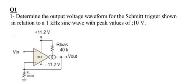
Transcribed Image Text:01
1- Determine the output voltage waveform for the Schmitt trigger shown
in relation to a 1 kHz sine wave with peak values of ;10 V.
+11.2 V
Rbias
40 k
Vin
OTA
-Vout
- 11.2 V
10 a
Expert Solution
This question has been solved!
Explore an expertly crafted, step-by-step solution for a thorough understanding of key concepts.

Step by step
Solved in 2 steps with 4 images

Knowledge Booster


Learn more about
Need a deep-dive on the concept behind this application? Look no further. Learn more about this topic, electrical-engineering and related others by exploring similar questions and additional content below.Recommended textbooks for you
Electricity for Refrigeration, Heating, and Air C…
Mechanical Engineering
ISBN:
9781337399128
Author:
Russell E. Smith
Publisher:
Cengage Learning
Electricity for Refrigeration, Heating, and Air C…
Mechanical Engineering
ISBN:
9781337399128
Author:
Russell E. Smith
Publisher:
Cengage Learning