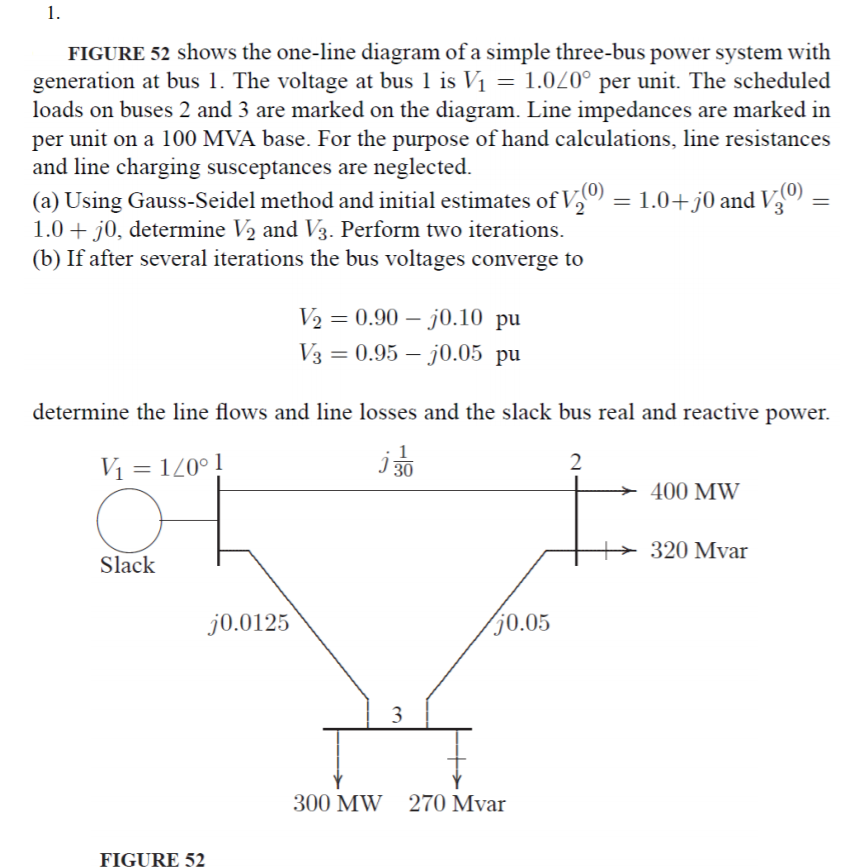
1. FIGURE 52 shows the one-line diagram of a simple three-bus power system with generation at bus I. The voltage at bus l is V1 = 1.0L0° per unit. The scheduled loads on buses 2 and 3 are marked on the diagram. Line impedances are marked in per unit on a 100 MVA base. For the purpose of hand calculations, line resistances and line charging susceptances are neglected a) Using Gauss-Seidel method and initial estimates of Va 0)-1.0+)0 and V o)- ( 1.0 +j0, determine V2 and V3. Perform two iterations (b) If after several iterations the bus voltages converge to V20.90-j0.10 pu 0.95-70.05 pu determine the line flows and line losses and the slack bus real and reactive power. 2 400 MW 320 Mvar Slack 0.0125 0.05 300 MW 270 Mvar FIGURE 52
1. FIGURE 52 shows the one-line diagram of a simple three-bus power system with generation at bus I. The voltage at bus l is V1 = 1.0L0° per unit. The scheduled loads on buses 2 and 3 are marked on the diagram. Line impedances are marked in per unit on a 100 MVA base. For the purpose of hand calculations, line resistances and line charging susceptances are neglected a) Using Gauss-Seidel method and initial estimates of Va 0)-1.0+)0 and V o)- ( 1.0 +j0, determine V2 and V3. Perform two iterations (b) If after several iterations the bus voltages converge to V20.90-j0.10 pu 0.95-70.05 pu determine the line flows and line losses and the slack bus real and reactive power. 2 400 MW 320 Mvar Slack 0.0125 0.05 300 MW 270 Mvar FIGURE 52

Power System Analysis and Design (MindTap Course List)
6th Edition
ISBN:9781305632134
Author:J. Duncan Glover, Thomas Overbye, Mulukutla S. Sarma
Publisher:J. Duncan Glover, Thomas Overbye, Mulukutla S. Sarma
Chapter6: Power Flows
Section: Chapter Questions
Problem 6.43P

Related questions
Question
Transcribed Image Text:1.
FIGURE 52 shows the one-line diagram of a simple three-bus power system with
generation at bus I. The voltage at bus l is V1 = 1.0L0° per unit. The scheduled
loads on buses 2 and 3 are marked on the diagram. Line impedances are marked in
per unit on a 100 MVA base. For the purpose of hand calculations, line resistances
and line charging susceptances are neglected
a) Using Gauss-Seidel method and initial estimates of Va
0)-1.0+)0 and V o)-
(
1.0 +j0, determine V2 and V3. Perform two iterations
(b) If after several iterations the bus voltages converge to
V20.90-j0.10 pu
0.95-70.05 pu
determine the line flows and line losses and the slack bus real and reactive power.
2
400 MW
320 Mvar
Slack
0.0125
0.05
300 MW
270 Mvar
FIGURE 52
Expert Solution


Trending now
This is a popular solution!

Step by step
Solved in 9 steps with 8 images

Recommended textbooks for you
Power System Analysis and Design (MindTap Course …
Electrical Engineering
ISBN:
9781305632134
Author:
J. Duncan Glover, Thomas Overbye, Mulukutla S. Sarma
Publisher:
Cengage Learning
Power System Analysis and Design (MindTap Course …
Electrical Engineering
ISBN:
9781305632134
Author:
J. Duncan Glover, Thomas Overbye, Mulukutla S. Sarma
Publisher:
Cengage Learning