1. In the crank arm of the figure, two loads P act as shown: one parallel to the x axis and another parallel to the y axis. Each load P equals 1.2 kN. The crankshaft dimensions are b1=75mm, b2=125mm and b3=35mm. The diameter of the upper shaft is 22mm a) Draw the stresses acting on the stress element A b) Determine the maximum tensile, compressive, and shear stresses at point A, which is located on the surface of the shaft at the z axis c) Draw the stresses acting on the stress element B d) Determine the maximum tensile, compressive, and shear stresses at point B, which is located on the surface of the shaft at the y axis bi b2 b3 In (-y) P In (-x) direction direction
1. In the crank arm of the figure, two loads P act as shown: one parallel to the x axis and another parallel to the y axis. Each load P equals 1.2 kN. The crankshaft dimensions are b1=75mm, b2=125mm and b3=35mm. The diameter of the upper shaft is 22mm a) Draw the stresses acting on the stress element A b) Determine the maximum tensile, compressive, and shear stresses at point A, which is located on the surface of the shaft at the z axis c) Draw the stresses acting on the stress element B d) Determine the maximum tensile, compressive, and shear stresses at point B, which is located on the surface of the shaft at the y axis bi b2 b3 In (-y) P In (-x) direction direction

Mechanics of Materials (MindTap Course List)
9th Edition
ISBN:9781337093347
Author:Barry J. Goodno, James M. Gere
Publisher:Barry J. Goodno, James M. Gere
Chapter3: Torsion
Section: Chapter Questions
Problem 3.5.12P: A solid aluminum bar (G = 27 GPa ) of diameter d = 40 mm is subjected to torques T = 300 N - m...

Related questions
Question
In the crank arm of the figure, two loads P act as shown: one parallel to the x axis and another parallel to the y axis. Each load P equals 1.2 kN. The crankshaft dimensions are b1=75mm, b2=125mmand b3=35mm. The diameter of the upper shaft is 22mm
Draw the stresses acting on the stress element A
b)
Determine the maximum tensile, compressive, and shear stresses at point A, which is located on the
surface of the shaft at the z axis
c)
Draw the stresses acting on the stress element B
d)
Determine the maximum tensile, compressive, and shear stresses at point B, which is located on the
surface of the shaft at the y axis
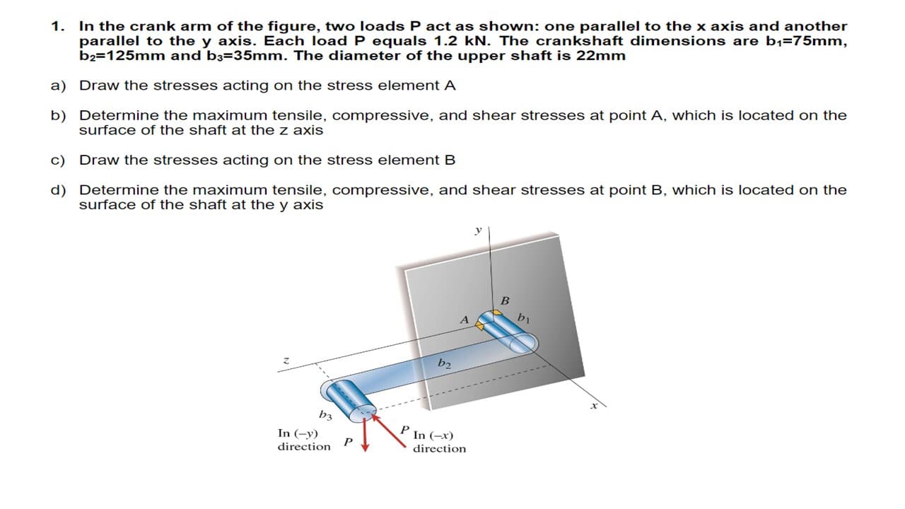
Transcribed Image Text:1. In the crank arm of the figure, two loads P act as shown: one parallel to the x axis and another
parallel to the y axis. Each load P equals 1.2 kN. The crankshaft dimensions are b1=75mm,
b2=125mm and b3=35mm. The diameter of the upper shaft is 22mm
a) Draw the stresses acting on the stress element A
b) Determine the maximum tensile, compressive, and shear stresses at point A, which is located on the
surface of the shaft at the z axis
c) Draw the stresses acting on the stress element B
d) Determine the maximum tensile, compressive, and shear stresses at point B, which is located on the
surface of the shaft at the y axis
bi
b2
b3
In (-y)
P In (-x)
direction
direction
Expert Solution
This question has been solved!
Explore an expertly crafted, step-by-step solution for a thorough understanding of key concepts.

This is a popular solution!

Trending now
This is a popular solution!

Step by step
Solved in 5 steps with 18 images

Knowledge Booster


Learn more about
Need a deep-dive on the concept behind this application? Look no further. Learn more about this topic, mechanical-engineering and related others by exploring similar questions and additional content below.Recommended textbooks for you
Mechanics of Materials (MindTap Course List)
Mechanical Engineering
ISBN:
9781337093347
Author:
Barry J. Goodno, James M. Gere
Publisher:
Cengage Learning
Mechanics of Materials (MindTap Course List)
Mechanical Engineering
ISBN:
9781337093347
Author:
Barry J. Goodno, James M. Gere
Publisher:
Cengage Learning