10.9 The collector characteristics for a certain transistor are shown in Figure P10.9. a. Find the ratio Ic/Ig for Vcg = 10 V and Ig = 100, 200, and 600 µA. b. The maximum allowable collector power dissipation is 0.5 W for Ig = 500 µA. Find Vce. ic, mA 100 90 600 μΑ. 80 500 µA 70 400 μΑ. 60 300 μΑ 50 40 200 µA 30 I3 = 100 µA 20 10 O 2 4 6 8 10 12 14 16 18 "CE, V Figure P10.9 Hint: A reasonable approximation for the power dissipated at the collector is the product of the collector voltage and current P = Ic VCE, where P is the permissible power dissipation, Ic is the quiescent collector current, and Vcg is the operating point collector-emitter voltage.
10.9 The collector characteristics for a certain transistor are shown in Figure P10.9. a. Find the ratio Ic/Ig for Vcg = 10 V and Ig = 100, 200, and 600 µA. b. The maximum allowable collector power dissipation is 0.5 W for Ig = 500 µA. Find Vce. ic, mA 100 90 600 μΑ. 80 500 µA 70 400 μΑ. 60 300 μΑ 50 40 200 µA 30 I3 = 100 µA 20 10 O 2 4 6 8 10 12 14 16 18 "CE, V Figure P10.9 Hint: A reasonable approximation for the power dissipated at the collector is the product of the collector voltage and current P = Ic VCE, where P is the permissible power dissipation, Ic is the quiescent collector current, and Vcg is the operating point collector-emitter voltage.

Introductory Circuit Analysis (13th Edition)
13th Edition
ISBN:9780133923605
Author:Robert L. Boylestad
Publisher:Robert L. Boylestad
Chapter1: Introduction
Section: Chapter Questions
Problem 1P: Visit your local library (at school or home) and describe the extent to which it provides literature...

Related questions
Question
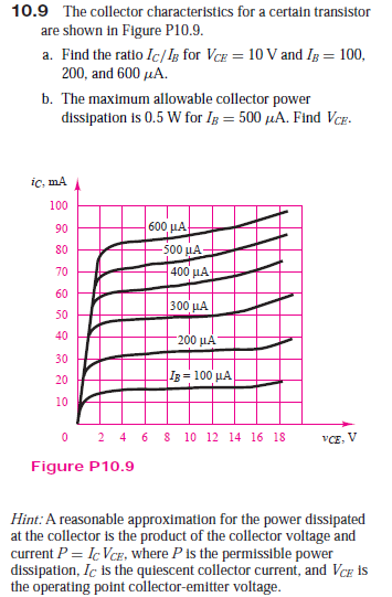
Transcribed Image Text:10.9 The collector characteristics for a certain transistor
are shown in Figure P10.9.
a. Find the ratio Ic/Ig for Vcg = 10 V and Ig = 100,
200, and 600 µA.
b. The maximum allowable collector power
dissipation is 0.5 W for Ig = 500 µA. Find Vce.
ic, mA
100
90
600 μΑ.
80
500 µA
70
400 μΑ.
60
300 μΑ
50
40
200 µA
30
I3 = 100 µA
20
10
O 2 4 6 8 10 12 14 16 18
"CE, V
Figure P10.9
Hint: A reasonable approximation for the power dissipated
at the collector is the product of the collector voltage and
current P = Ic VCE, where P is the permissible power
dissipation, Ic is the quiescent collector current, and Vcg is
the operating point collector-emitter voltage.
Expert Solution
This question has been solved!
Explore an expertly crafted, step-by-step solution for a thorough understanding of key concepts.

This is a popular solution!

Trending now
This is a popular solution!

Step by step
Solved in 3 steps with 8 images

Recommended textbooks for you
Introductory Circuit Analysis (13th Edition)
Electrical Engineering
ISBN:
9780133923605
Author:
Robert L. Boylestad
Publisher:
PEARSON

Delmar's Standard Textbook Of Electricity
Electrical Engineering
ISBN:
9781337900348
Author:
Stephen L. Herman
Publisher:
Cengage Learning

Programmable Logic Controllers
Electrical Engineering
ISBN:
9780073373843
Author:
Frank D. Petruzella
Publisher:
McGraw-Hill Education
Introductory Circuit Analysis (13th Edition)
Electrical Engineering
ISBN:
9780133923605
Author:
Robert L. Boylestad
Publisher:
PEARSON
Delmar's Standard Textbook Of Electricity
Electrical Engineering
ISBN:
9781337900348
Author:
Stephen L. Herman
Publisher:
Cengage Learning
Programmable Logic Controllers
Electrical Engineering
ISBN:
9780073373843
Author:
Frank D. Petruzella
Publisher:
McGraw-Hill Education

Fundamentals of Electric Circuits
Electrical Engineering
ISBN:
9780078028229
Author:
Charles K Alexander, Matthew Sadiku
Publisher:
McGraw-Hill Education

Electric Circuits. (11th Edition)
Electrical Engineering
ISBN:
9780134746968
Author:
James W. Nilsson, Susan Riedel
Publisher:
PEARSON

Engineering Electromagnetics
Electrical Engineering
ISBN:
9780078028151
Author:
Hayt, William H. (william Hart), Jr, BUCK, John A.
Publisher:
Mcgraw-hill Education,