2. Electric power is to be generated in a hydroelectric power plant that receives water at a rate of 70 m/s from an elevation of 65 m using a turbine-generator with an efficiency of 85 percent. When frictional losses in piping are disregarded, the electric power output of this plant is (a)3.9 MW (b) 38 MW (c) 45 MW (d) 53 MW (e) 65 MW
2. Electric power is to be generated in a hydroelectric power plant that receives water at a rate of 70 m/s from an elevation of 65 m using a turbine-generator with an efficiency of 85 percent. When frictional losses in piping are disregarded, the electric power output of this plant is (a)3.9 MW (b) 38 MW (c) 45 MW (d) 53 MW (e) 65 MW

Elements Of Electromagnetics
7th Edition
ISBN:9780190698614
Author:Sadiku, Matthew N. O.
Publisher:Sadiku, Matthew N. O.
ChapterMA: Math Assessment
Section: Chapter Questions
Problem 1.1MA

Related questions

Question
Transcribed Image Text:Q2
1. Drive the relation
mt Vavg - mg Vg
- vg
Vfg =
mf
2. Electric power is to be generated in a hydroelectric power plant that receives
water at a rate of 70 m'/s from an elevation of 65 m using a turbine-generator with
an efficiency of 85 percent. When frictional losses in piping are disregarded, the
electric power output of this plant is
(a)3.9 MW (b) 38 MW (c) 45 MW
(d) 53 MW
(e) 65 MW
3. What is the difference between the classical and the statistical approaches to
thermodynamics?
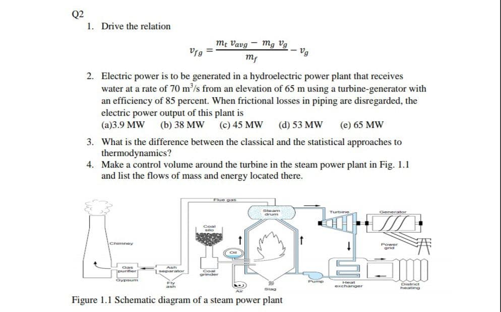
4. Make a control volume around the turbine in the steam power plant in Fig. 1.1
and list the flows of mass and energy located there.
Flue gas
Steam
Generator
Turbine
unup
Coal
Silo
Chimney
Power
grid
Gas
Ash
purifier
Coal
grinder
1
separator
Gypsum
Pump
District
heating
Heat
Fly
ash
exchanger
Slag
Air
Figure 1.1 Schematic diagram of a steam power plant
Expert Solution
This question has been solved!
Explore an expertly crafted, step-by-step solution for a thorough understanding of key concepts.

This is a popular solution!

Trending now
This is a popular solution!

Step by step
Solved in 3 steps with 2 images

Knowledge Booster


Learn more about
Need a deep-dive on the concept behind this application? Look no further. Learn more about this topic, mechanical-engineering and related others by exploring similar questions and additional content below.Recommended textbooks for you
Elements Of Electromagnetics
Mechanical Engineering
ISBN:
9780190698614
Author:
Sadiku, Matthew N. O.
Publisher:
Oxford University Press

Mechanics of Materials (10th Edition)
Mechanical Engineering
ISBN:
9780134319650
Author:
Russell C. Hibbeler
Publisher:
PEARSON

Thermodynamics: An Engineering Approach
Mechanical Engineering
ISBN:
9781259822674
Author:
Yunus A. Cengel Dr., Michael A. Boles
Publisher:
McGraw-Hill Education
Elements Of Electromagnetics
Mechanical Engineering
ISBN:
9780190698614
Author:
Sadiku, Matthew N. O.
Publisher:
Oxford University Press
Mechanics of Materials (10th Edition)
Mechanical Engineering
ISBN:
9780134319650
Author:
Russell C. Hibbeler
Publisher:
PEARSON
Thermodynamics: An Engineering Approach
Mechanical Engineering
ISBN:
9781259822674
Author:
Yunus A. Cengel Dr., Michael A. Boles
Publisher:
McGraw-Hill Education

Control Systems Engineering
Mechanical Engineering
ISBN:
9781118170519
Author:
Norman S. Nise
Publisher:
WILEY

Mechanics of Materials (MindTap Course List)
Mechanical Engineering
ISBN:
9781337093347
Author:
Barry J. Goodno, James M. Gere
Publisher:
Cengage Learning

Engineering Mechanics: Statics
Mechanical Engineering
ISBN:
9781118807330
Author:
James L. Meriam, L. G. Kraige, J. N. Bolton
Publisher:
WILEY