3 For the simply supported beam shown in the figure, point (C) may represent a point of contraflexure
3 For the simply supported beam shown in the figure, point (C) may represent a point of contraflexure

Mechanics of Materials (MindTap Course List)
9th Edition
ISBN:9781337093347
Author:Barry J. Goodno, James M. Gere
Publisher:Barry J. Goodno, James M. Gere
Chapter10: Statically Indeterminate Beams
Section: Chapter Questions
Problem 10.4.25P: A beam ABC is fixed at end A and supported by beam DE at point B (sec figure). Both beams have the...

Related questions

Question
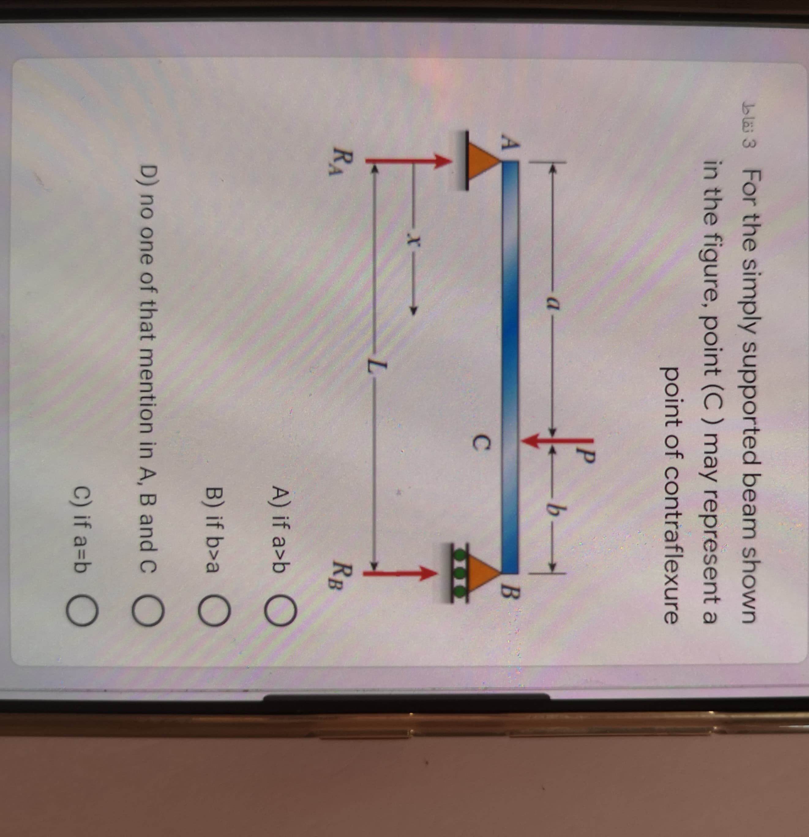
Transcribed Image Text:3 For the simply supported beam shown
in the figure, point (C) may represent a
point of contraflexure
Expert Solution
This question has been solved!
Explore an expertly crafted, step-by-step solution for a thorough understanding of key concepts.

This is a popular solution!

Trending now
This is a popular solution!

Step by step
Solved in 2 steps with 3 images

Knowledge Booster


Learn more about
Need a deep-dive on the concept behind this application? Look no further. Learn more about this topic, mechanical-engineering and related others by exploring similar questions and additional content below.Recommended textbooks for you
Mechanics of Materials (MindTap Course List)
Mechanical Engineering
ISBN:
9781337093347
Author:
Barry J. Goodno, James M. Gere
Publisher:
Cengage Learning
Mechanics of Materials (MindTap Course List)
Mechanical Engineering
ISBN:
9781337093347
Author:
Barry J. Goodno, James M. Gere
Publisher:
Cengage Learning