3) The single-line diagram of a three-phase system is given in Figure 3. The three-phase generator is rated 4160 kVA, 2.4 kV, and 1000 A. The three-phase transformer T1 is rated 6000 kVA, 2.4Y/24Y kV, with leakage reactance of 0.04 pu. Transformer T2 is made up of three single-phase transformers and is rated 4000 kVA, 24Y/12Y kV, with leakage reactance of 0.04 pu. The load draws 2000KVA with 0.8 PF leading at 12kV. Assume that the line length between the two transformers is negligible. Select a base power value and base voltages DIFFERENT than the ratings of the equipment. Determine the following for all three circuits, 2.4-, 24-, and 12-kV circuits: (a) Base impedance values (b) Base current values (c) Per-unit and actual current values (neglect magnetizing currents in transformers and charging currents in lines) (d) Per-unit and actual voltage values at buses 1, 2, and 4 (e) Per-unit and actual apparent power values at buses 1, 2, and 4 24 kV N1 N2 2.4 kV 24 kV 12 kV N2 N1 Load T1 T2 Figure 3
3) The single-line diagram of a three-phase system is given in Figure 3. The three-phase generator is rated 4160 kVA, 2.4 kV, and 1000 A. The three-phase transformer T1 is rated 6000 kVA, 2.4Y/24Y kV, with leakage reactance of 0.04 pu. Transformer T2 is made up of three single-phase transformers and is rated 4000 kVA, 24Y/12Y kV, with leakage reactance of 0.04 pu. The load draws 2000KVA with 0.8 PF leading at 12kV. Assume that the line length between the two transformers is negligible. Select a base power value and base voltages DIFFERENT than the ratings of the equipment. Determine the following for all three circuits, 2.4-, 24-, and 12-kV circuits: (a) Base impedance values (b) Base current values (c) Per-unit and actual current values (neglect magnetizing currents in transformers and charging currents in lines) (d) Per-unit and actual voltage values at buses 1, 2, and 4 (e) Per-unit and actual apparent power values at buses 1, 2, and 4 24 kV N1 N2 2.4 kV 24 kV 12 kV N2 N1 Load T1 T2 Figure 3

Power System Analysis and Design (MindTap Course List)
6th Edition
ISBN:9781305632134
Author:J. Duncan Glover, Thomas Overbye, Mulukutla S. Sarma
Publisher:J. Duncan Glover, Thomas Overbye, Mulukutla S. Sarma
Chapter3: Power Transformers
Section: Chapter Questions
Problem 3.48P: With the same transformer banks as in Problem 3.47, Figure 3.41 shows the oneline diagram of a...

Related questions

Question
Thank you ..
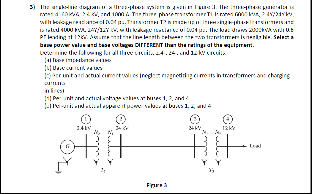
Transcribed Image Text:3) The single-line diagram of a three-phase system is given in Figure 3. The three-phase generator is
rated 4160 kVA, 2.4 kV, and 1000 A. The three-phase transformer T1 is rated 6000 kVA, 2.4Y/24Y kV,
with leakage reactance of 0.04 pu. Transformer T2 is made up of three single-phase transformers and
is rated 4000 kVA, 24Y/12Y kV, with leakage reactance of 0.04 pu. The load draws 2000KVA with 0.8
PF leading at 12kV. Assume that the line length between the two transformers is negligible. Select a
base power value and base voltages DIFFERENT than the ratings of the equipment.
Determine the following for all three circuits, 2.4-, 24-, and 12-kV circuits:
(a) Base impedance values
(b) Base current values
(c) Per-unit and actual current values (neglect magnetizing currents in transformers and charging
currents
in lines)
(d) Per-unit and actual voltage values at buses 1, 2, and 4
(e) Per-unit and actual apparent power values at buses 1, 2, and 4
24 kV
N1 N2
2.4 kV
24 kV
12 kV
N2 N1
Load
T1
T2
Figure 3
Expert Solution
This question has been solved!
Explore an expertly crafted, step-by-step solution for a thorough understanding of key concepts.

This is a popular solution!

Trending now
This is a popular solution!

Step by step
Solved in 5 steps with 4 images

Knowledge Booster


Learn more about
Need a deep-dive on the concept behind this application? Look no further. Learn more about this topic, electrical-engineering and related others by exploring similar questions and additional content below.Recommended textbooks for you
Power System Analysis and Design (MindTap Course …
Electrical Engineering
ISBN:
9781305632134
Author:
J. Duncan Glover, Thomas Overbye, Mulukutla S. Sarma
Publisher:
Cengage Learning

Delmar's Standard Textbook Of Electricity
Electrical Engineering
ISBN:
9781337900348
Author:
Stephen L. Herman
Publisher:
Cengage Learning
Power System Analysis and Design (MindTap Course …
Electrical Engineering
ISBN:
9781305632134
Author:
J. Duncan Glover, Thomas Overbye, Mulukutla S. Sarma
Publisher:
Cengage Learning
Delmar's Standard Textbook Of Electricity
Electrical Engineering
ISBN:
9781337900348
Author:
Stephen L. Herman
Publisher:
Cengage Learning