3. Heat Loss from Longitudinal Fin. A longitudinal aluminum fin, as shown in Fig. 15.8-3a (k = 230 W/m K), is attached to a copper tube having of 0.04 m. The length of the fin is 0.080 m and the thickness is 3 mm. The tube base is held at 450 K and the external surrounding air at 300 K has a convective coefficient of 25 W/m2 K. Calculate the fin efficiency and the heat loss from the fin per 1.0 m of length. an outside radius AM .a a 0.039 B = 0.70 for nonviscous liquids where D = diameter of the vessel in m, Ds = diameter of the rotating shaft in m, v = the axial flow velocity of liquid in m/s, N = the agitator speed in rev/s, and nB on the agitator. Data cover a region of axial flow velocities of 0.076 to 0.38 m/min and rota- tional speeds of 100 to 750 rpm. Typical overall heat-transfer coefficients in food applications are U = 1700 W/m2 K the number of blades (300 btu/h ft F) for cooling margarine with NH3, 2270 (400) for heating applesauce with steam, 1420 (250) for chilling shortening with NH3, and 2270 (400) for cooling cream with water (B6). 15.8C Extended Surface or Finned Exchangers 1. Introduction. The use of fins or extended surfaces on the outside of a heat-exchanger pipe wall to give relatively high heat-transfer coefficients in the exchanger is quite common. An automobile radiator is such a device, where hot water passes inside through a bank of tubes and loses heat to the air. On the outside of the tubes, extended surfaces receive heat from the tube walls and transmit it to the air by forced convection. Two common types of fins attached to the outside of a tube wall are shown in Fig. 15.8-3. In Fig, 15.8-3a, there are a number of longitudinal fins spaced around the tube wall and the direction of gas flow is parallel to the axis of the tube. In Fig. 15.8-3b, the gas flows normally to the tubes containing many circular or transverse fins. fin fin 058-13) L tube S10 tube (b) (a) Figure 15.8-3. Two common types of fins on a section of circular tube: (a) longitudinal fin, (b) circular or transverse fin. Part 1 Transport Processes: Momentum, Heat, and Mass 431
3. Heat Loss from Longitudinal Fin. A longitudinal aluminum fin, as shown in Fig. 15.8-3a (k = 230 W/m K), is attached to a copper tube having of 0.04 m. The length of the fin is 0.080 m and the thickness is 3 mm. The tube base is held at 450 K and the external surrounding air at 300 K has a convective coefficient of 25 W/m2 K. Calculate the fin efficiency and the heat loss from the fin per 1.0 m of length. an outside radius AM .a a 0.039 B = 0.70 for nonviscous liquids where D = diameter of the vessel in m, Ds = diameter of the rotating shaft in m, v = the axial flow velocity of liquid in m/s, N = the agitator speed in rev/s, and nB on the agitator. Data cover a region of axial flow velocities of 0.076 to 0.38 m/min and rota- tional speeds of 100 to 750 rpm. Typical overall heat-transfer coefficients in food applications are U = 1700 W/m2 K the number of blades (300 btu/h ft F) for cooling margarine with NH3, 2270 (400) for heating applesauce with steam, 1420 (250) for chilling shortening with NH3, and 2270 (400) for cooling cream with water (B6). 15.8C Extended Surface or Finned Exchangers 1. Introduction. The use of fins or extended surfaces on the outside of a heat-exchanger pipe wall to give relatively high heat-transfer coefficients in the exchanger is quite common. An automobile radiator is such a device, where hot water passes inside through a bank of tubes and loses heat to the air. On the outside of the tubes, extended surfaces receive heat from the tube walls and transmit it to the air by forced convection. Two common types of fins attached to the outside of a tube wall are shown in Fig. 15.8-3. In Fig, 15.8-3a, there are a number of longitudinal fins spaced around the tube wall and the direction of gas flow is parallel to the axis of the tube. In Fig. 15.8-3b, the gas flows normally to the tubes containing many circular or transverse fins. fin fin 058-13) L tube S10 tube (b) (a) Figure 15.8-3. Two common types of fins on a section of circular tube: (a) longitudinal fin, (b) circular or transverse fin. Part 1 Transport Processes: Momentum, Heat, and Mass 431

Principles of Heat Transfer (Activate Learning with these NEW titles from Engineering!)
8th Edition
ISBN:9781305387102
Author:Kreith, Frank; Manglik, Raj M.
Publisher:Kreith, Frank; Manglik, Raj M.
Chapter10: Heat Exchangers
Section: Chapter Questions
Problem 10.8P:
10.8 The heat transfer coefficient of a copper tube (1.9-cm II) and 2.3-em OD) is on the inside...

Related questions
Question
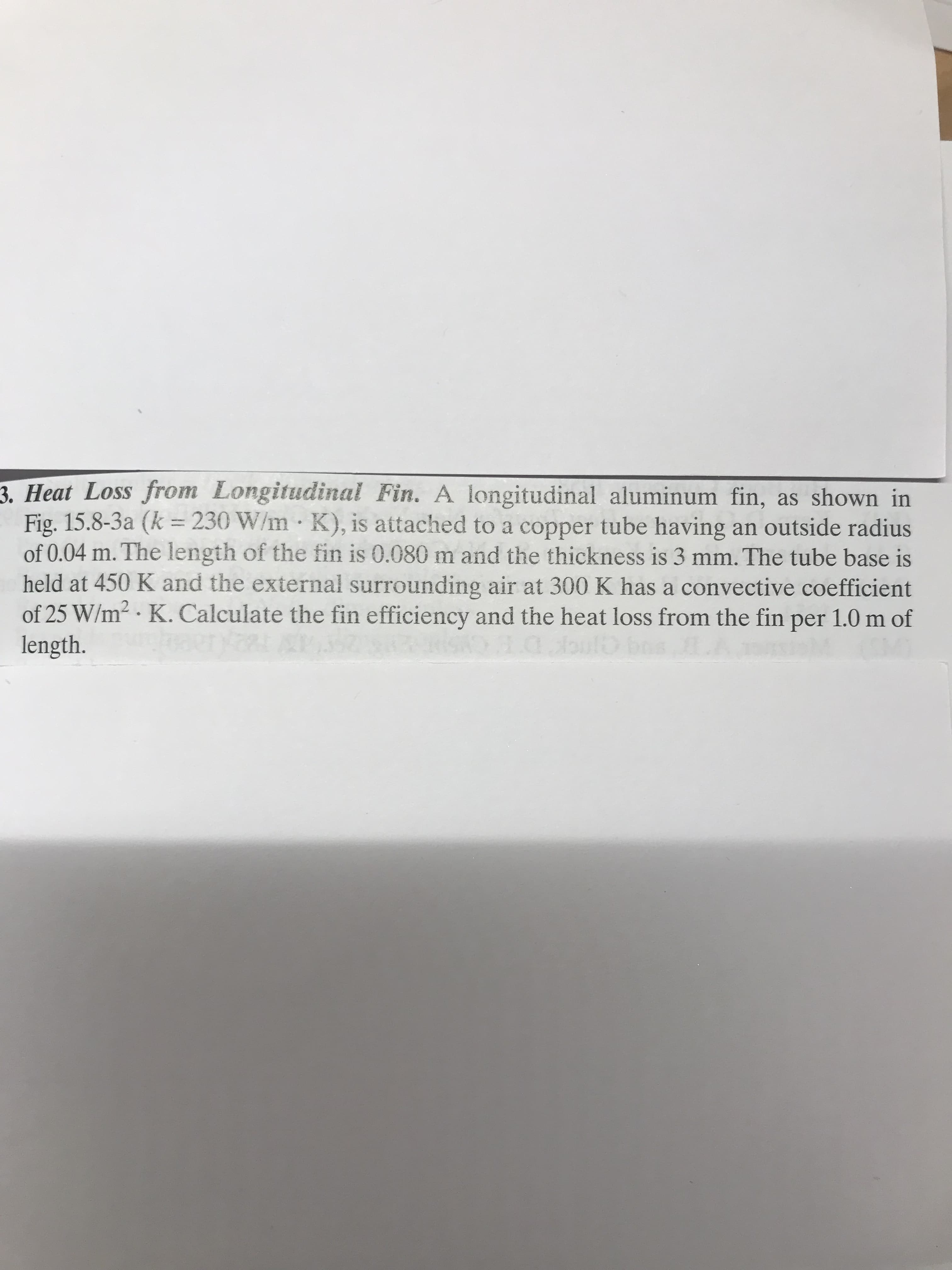
Transcribed Image Text:3. Heat Loss from Longitudinal Fin. A longitudinal aluminum fin, as shown in
Fig. 15.8-3a (k = 230 W/m K), is attached to a copper tube having
of 0.04 m. The length of the fin is 0.080 m and the thickness is 3 mm. The tube base is
held at 450 K and the external surrounding air at 300 K has a convective coefficient
of 25 W/m2 K. Calculate the fin efficiency and the heat loss from the fin per 1.0 m of
length.
an outside radius
AM
.a
Transcribed Image Text:a 0.039 B = 0.70
for nonviscous liquids
where D = diameter of the vessel in m, Ds = diameter of the rotating shaft in m, v = the axial
flow velocity of liquid in m/s, N = the agitator speed in rev/s, and nB
on the agitator. Data cover a region of axial flow velocities of 0.076 to 0.38 m/min and rota-
tional speeds of 100 to 750 rpm.
Typical overall heat-transfer coefficients in food applications are U = 1700 W/m2 K
the number of blades
(300 btu/h ft F) for cooling margarine with NH3, 2270 (400) for heating applesauce with
steam, 1420 (250) for chilling shortening with NH3, and 2270 (400) for cooling cream with
water (B6).
15.8C Extended Surface or Finned Exchangers
1. Introduction. The use of fins or extended surfaces on the outside of a heat-exchanger
pipe wall to give relatively high heat-transfer coefficients in the exchanger is quite common.
An automobile radiator is such a device, where hot water passes inside through a bank of
tubes and loses heat to the air. On the outside of the tubes, extended surfaces receive heat
from the tube walls and transmit it to the air by forced convection.
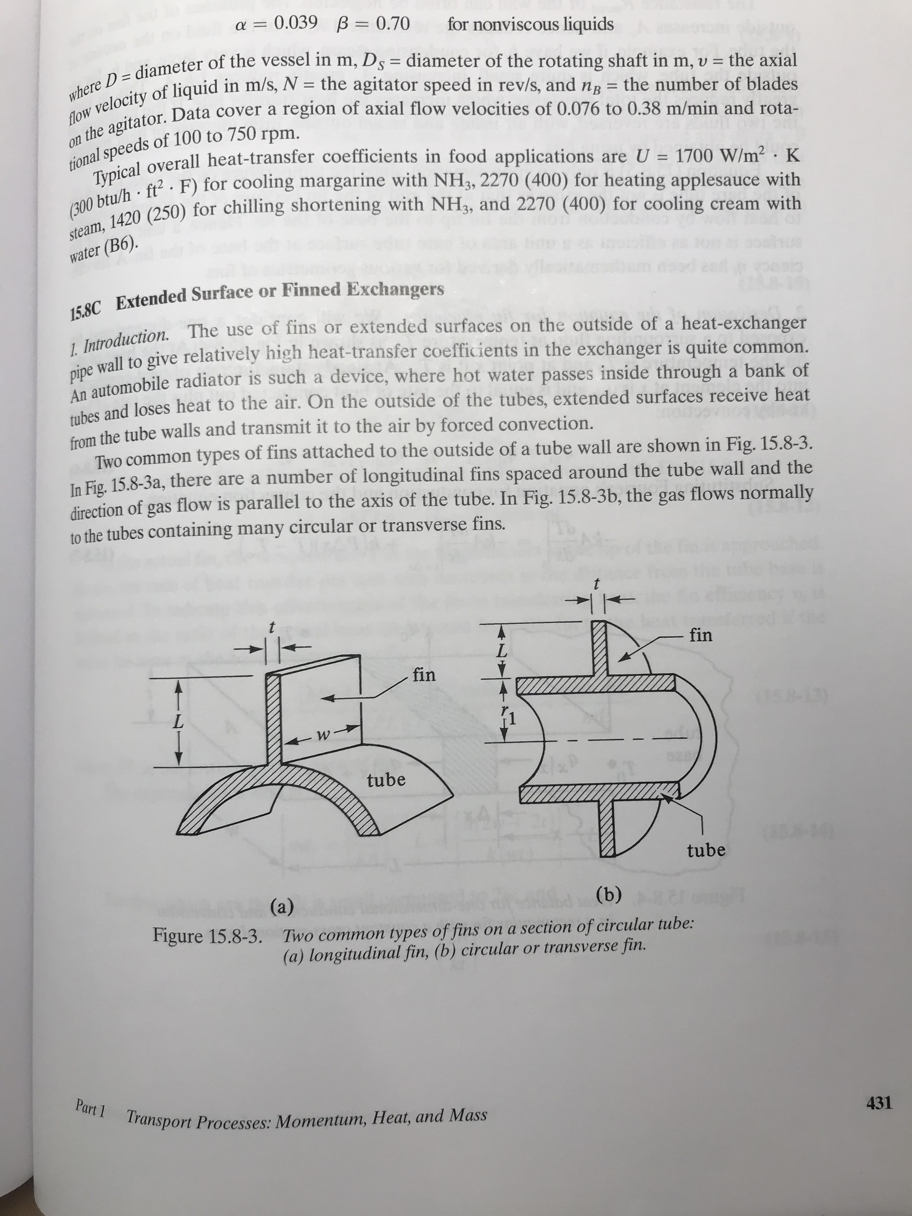
Two common types of fins attached to the outside of a tube wall are shown in Fig. 15.8-3.
In Fig, 15.8-3a, there are a number of longitudinal fins spaced around the tube wall and the
direction of gas flow is parallel to the axis of the tube. In Fig. 15.8-3b, the gas flows normally
to the tubes containing many circular or transverse fins.
fin
fin
058-13)
L
tube
S10
tube
(b)
(a)
Figure 15.8-3.
Two common types of fins on a section of circular tube:
(a) longitudinal fin, (b) circular or transverse fin.
Part 1 Transport Processes: Momentum, Heat, and Mass
431
Expert Solution
This question has been solved!
Explore an expertly crafted, step-by-step solution for a thorough understanding of key concepts.

This is a popular solution!

Trending now
This is a popular solution!

Step by step
Solved in 6 steps with 4 images

Recommended textbooks for you
Principles of Heat Transfer (Activate Learning wi…
Mechanical Engineering
ISBN:
9781305387102
Author:
Kreith, Frank; Manglik, Raj M.
Publisher:
Cengage Learning
Principles of Heat Transfer (Activate Learning wi…
Mechanical Engineering
ISBN:
9781305387102
Author:
Kreith, Frank; Manglik, Raj M.
Publisher:
Cengage Learning