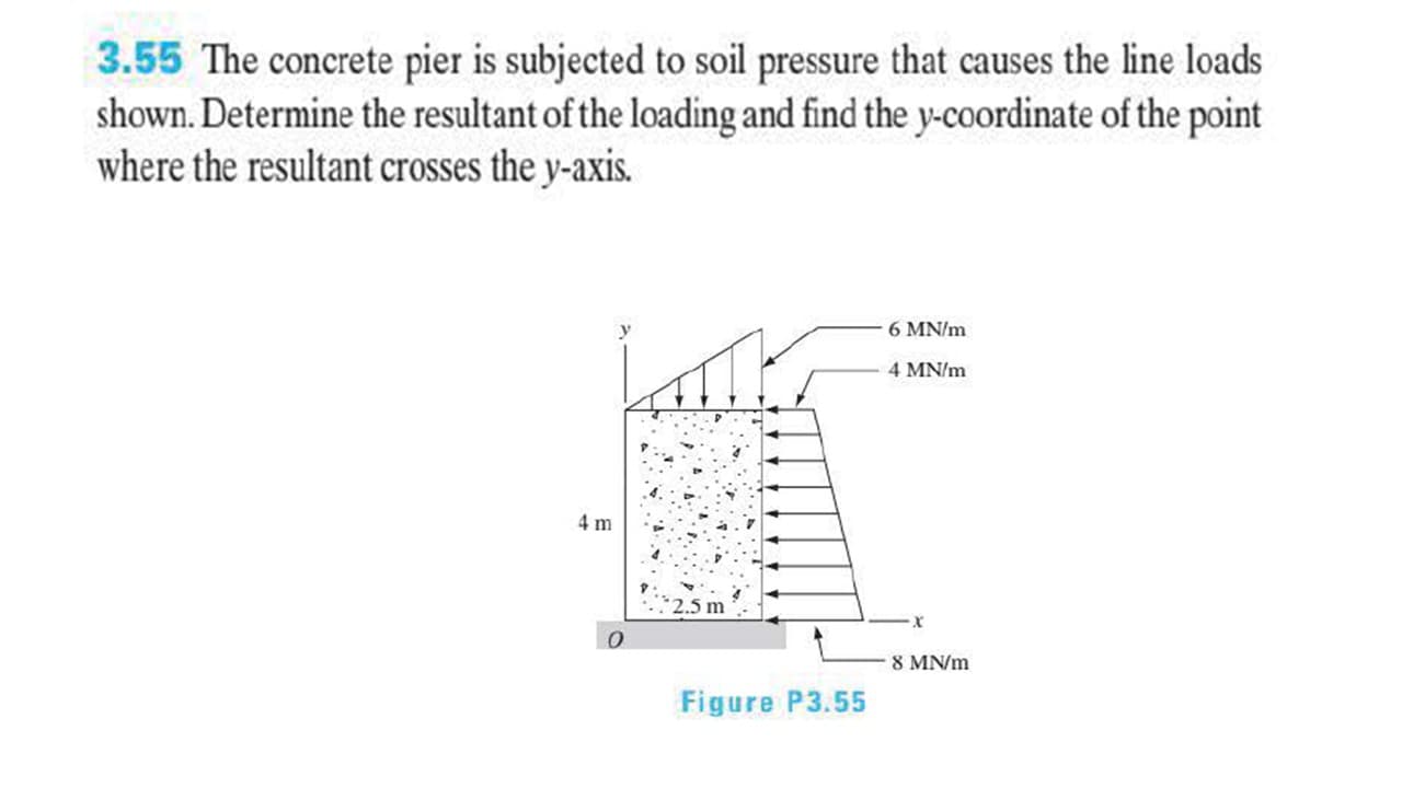
3.55 The concrete pier is subjected to soil pressure that causes the line loads shown. Determine the resultant of the loading and find the y-coordinate of the point where the resultant crosses the y-axis. 6 MN/m 4 MN/m 4 m 8 MN/m Figure P3.55
3.55 The concrete pier is subjected to soil pressure that causes the line loads shown. Determine the resultant of the loading and find the y-coordinate of the point where the resultant crosses the y-axis. 6 MN/m 4 MN/m 4 m 8 MN/m Figure P3.55

Principles of Geotechnical Engineering (MindTap Course List)
9th Edition
ISBN:9781305970939
Author:Braja M. Das, Khaled Sobhan
Publisher:Braja M. Das, Khaled Sobhan
Chapter15: Slope Stability
Section: Chapter Questions
Problem 15.28P

Related questions
Question
Transcribed Image Text:3.55 The concrete pier is subjected to soil pressure that causes the line loads
shown. Determine the resultant of the loading and find the y-coordinate of the point
where the resultant crosses the y-axis.
6 MN/m
4 MN/m
4 m
8 MN/m
Figure P3.55
Expert Solution
This question has been solved!
Explore an expertly crafted, step-by-step solution for a thorough understanding of key concepts.

This is a popular solution!

Trending now
This is a popular solution!

Step by step
Solved in 3 steps with 5 images

Recommended textbooks for you
Principles of Geotechnical Engineering (MindTap C…
Civil Engineering
ISBN:
9781305970939
Author:
Braja M. Das, Khaled Sobhan
Publisher:
Cengage Learning
Principles of Geotechnical Engineering (MindTap C…
Civil Engineering
ISBN:
9781305970939
Author:
Braja M. Das, Khaled Sobhan
Publisher:
Cengage Learning