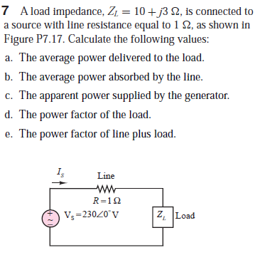
7 A load impedance, Z1 = 10 + j3 2, is connected to a source with line resistance equal to 1 N, as shown in Figure P7.17. Calculate the following values: a. The average power delivered to the load. b. The average power absorbed by the line. c. The apparent power supplied by the generator. d. The power factor of the load. e. The power factor of line plus load. Line ww R=12 Vs =23020'V Z, Load
Q: 2. A Y-connected balanced 3-phase source is supplying a balanced 3-phase load. The source phase A…
A: For Star connected system, Phase voltage = line voltage/sqrt(3). Line current = phase current. For…
Q: Draw the relevant diagram and label all entity values of the power system as described above. (b)…
A:
Q: L-type equivalent circuit and parameters for a continuous sinusoidal phase of a 5.5 kW, 1450 rpm,…
A: First we will calculate impedance ssen by the source and than we will find current from source in…
Q: Q3. The load impedance in the circuit shown in Figure 2 is shunted by a capacitor having a…
A:
Q: L-type equivalent circuit and parameters for a continuous sinusoidal phase of a 5.5 kW, 1480 rpm,…
A:
Q: of the series connection of the resistor R0 and the inductance L0 between the terminals a and b.…
A: In this question we will find average power delivered to load..
Q: A generating station supplies the following loads: 15000 kW, 12000 kW, 8500 kW, 6000 kW and 450 kW.…
A: Total loads are 15000 kW, 12000 kW, 8500 kW, 6000 kW and 450 kW.
Q: A man has a body resistance of 600 N. How much current flows through his ungrounded body: (a) when…
A: The solution can be achieved as follows.
Q: d) The generated voltage of a turbine at time t seconds is given by: v(t) = Vgsin(0.4nt + Where Vs…
A:
Q: There is a load formed by the series connection of the resistor R0 and the inductance L0 between the…
A:
Q: Suppose the circuit shown represents a residential distribution circuit in which the impedances of…
A:
Q: Using rms values to represent their magnitudes, the voltage across and the current into a load are-…
A: We are authorized to answer one question at a time since you have not mentioned which question you…
Q: d. What are the line currents (laa, IbB, lec)? e. What real, reactive and apparent power does the…
A:
Q: There is a load formed by the series connection of the resistor R0 and the inductance L0 between the…
A:
Q: R = 2 kN E = 282 sen (100at) 40 L =- H r = 2 kN 10 C =- µF
A:
Q: phase. The voltage of power station A is advanced with an angle of 10.5 degrees with respect to the…
A:
Q: The voltage V, in the frequency-domain circuit shown in (Figure 1) is 120./0° V (ms). • Part A Find…
A:
Q: Consider the problem of maximizing the average power Z = R+jX absorbed by the load impedance Zjoad=…
A: (a) Given circuit is – Given values are –
Q: In the circuit in the figure, there is a load consisting of the series connection of the resistor R0…
A: Given circuit shown with Voltage source Amplitute =1502 vPhase angle θs=0°Time period T=200π μsR=300…
Q: 7. A power station has to meet the following load demand 50 KW 30 kW 20 kW between 10 A.M. and 6PM.…
A: Load A 50KW 10AM to 6PM Load B 30KW 6PM to 10PM Load C 20KW 4PM to 10AM Draw load curve, diversity…
Q: I Review | Constants The steady-state voltage drop between the load and the sending end of the line…
A:
Q: A 25 kVA, 240 V single phase source supply the rated power at the rated voltage to a motor at 0.8…
A: As we have given : S=25 kVAV=240 Vcosϕ1=0.8cosϕ2=0.9
Q: For the system shown in figure, voltages V2. V3 and angles 82 83 are calculated using Newton-Raphson…
A: The given system diagram is shown below,…
Q: Q3//A// Peak demand of generating station is 90MW and the load factor is 0.6. The plant capacity…
A: The solution can be achieved as follows.
Q: The load impedance in the circuit shown is shunted by a capacitor having a capacitive reac- tance of…
A: In Network Phasor load current and voltage Real and imaginary power across load , transmission…
Q: ) The load, ZL, that will provide the maximum power to it b) The average power delivered to the…
A:
Q: The peak value of the reactive component of power transmitted, that is forever travelling backward…
A: The peak value of the reactive component of power transmitted that is forever travelling backward…
Q: 4 For the circuit of Figure P7.13, determine the power factor for the load and state whether it is…
A: As per our honor code, we have asked to answer only three parts of the question. Please specify the…
Q: Between the terminals a and b in the figure, there is a load formed by connecting the resistor R0…
A:
Q: The instantaneous voltage across a circuit element is v(t) - 359.3 sin(wt + 15°) volts, and the…
A:
Q: the circuit in the figure, there is a load consisting of the series connection of the resistor R0…
A: In this question , we will find load value for maximum power deliver to load and maximum power…
Q: 1.3. The annual load of a substation is given in the following table. During each month, the power…
A: Below are the codes required to generate the load curve using barcycle function.
Q: L-type equivalent circuit and parameters for a continuous sinusoidal phase of a 5.5 kW, 1420 rpm,…
A: The slip of the three-phase ASM is calculated as shown below: Ns=120fPP=4f=50…
Q: 7.17 A load impedance, Z, = 10+ j3 2, is connected to a source with line resistance equal to1 2, as…
A:
Q: R. Yük
A: a) we need to find our L0 and R0
Q: 7.76 A three-phase motor is modeled by the wye-connected circult shown in Figure P7.76. At t = t1, a…
A: (a) For t << t1, Find the value of current IR, IW, and IB as below. And, And,
Q: In the circuit in the figure, there is a load consisting of the series connection of the resistor R0…
A:
Q: a) A source voltage of 230V rms at 50HZ is applied to a circuit having an impedance of (10+j12)…
A:
Q: For the maximum average power transfer in the circuit shown in Figure 2, use the impedance ZL and ZL…
A:
Q: QUA power plant has to meet the following load demand: Load A: 100 MW from 8 AM - 6 PM Load B: 150…
A:
Q: Electrical load that draws current whose impedance varies throughout the cycle of the input ac…
A: Correct option is TRUE we know that Non linear loads draws non linear current whose impedance is…
Q: For the circuit shown, given that Vab=208Z°, abc sequence, ZLine%3D0.1+j0.2 Q and ZLoad= 12+j4 Q.…
A: Magnitude of voltage VAB across load? 3 phase power system
Q: B) Four regions of peak loads 5 MW, 7 MW, 8 MW and 10 MW are supplied by a generating station. The…
A: Peak loads are given, 5 MW, 7 MW, 8 MW, 10 MW. Average load factor LF = 0.6 Diversity factor DF =…
Q: a. If i = Im sin wt is flowing through a series R-L branch, then derive the expression for voltage,…
A: The circuit this is excited the use of alternating supply is referred to as an AC Circuit. The…
Q: In the circuit in the figure, there is a load consisting of the series connection of the resistor R0…
A:
Q: 4 For the circuit of Figure P7.23, determine the power factor for the load and state whether it is…
A: Hello. Since your question has multiple sub-parts, we will solve the first three sub-parts for you.…
Q: For the system shown in figure, voltages V2, V3 and angles 82, 83 are calculated using…
A:
Q: A 3-phase overhead transmission line is being supported by three disc insulators. The potentials…
A: Given:-potential across top unit =9kv=v1potential across middle unit=11kv=v2& there are 3 disc…
Q: The estimated short circuit MVA at the bus bars of a generating station A is 1500 MVA and of…
A:
Q: H. W.: A 3-phase overhead transmission line is being supported by three disc insulators. The…
A: Given, Number of insulator disc (n)=3 Voltage across the top unit (V1)= 9 kV Voltage across the…
Trending now
This is a popular solution!
Step by step
Solved in 6 steps with 6 images
- Which termination would result to a phase change of 180 degrees at the load if Zo = 100 ohm? a. 50 ohm b. short circuit c. 75 ohm d. all of these What is the purpose of impedance matching? a. maximum return loss b. maximum SWR c. maximum load power d. maximum reflection A short piece of transmission line that may be open or shorted and used for impedance matching purposes. a. converter b. decoder c. stub d. transformerThe sending-end voltage in the circuit seen is adjusted so that the load voltage is always 13,800 V(rms). The variable capacitor is adjusted until the average power dissipated in the line resistance is minimum. 1. a) If the frequency of the sinusoidal source is 60 Hz, what is thevalue of the capacitance in microfarads?2. b) If the capacitor is removed from the circuit, what percentageincrease in the magnitude of Vs is necessary to maintain 13,800V(rms) at the load?3. c) If the capacitor is removed from the circuit, what is thepercentage increase in line loss?The estimated short circuit MVA at the bus bars of a generating station A is 1500 MVA and of another station B is 1200 MVA. The generated voltage at each stations is 33 kV. If these stations are interconnected through a line having a reactance of 1 ohm and negligible resistance, calculate the possible short circuit MVA at station B. (1831MVA)
- The voltage v(t)=359.3cos(t)volts is applied to a load consisting of a 10 resistor in parallel with a capacitive reactance XC=25. Calculate (a) the instantaneous power absorbed by the resistor, (b) the instantaneous power absorbed by the capacitor. (c) the real power absorbed by the resistor, (d) the reactive power delivered by the capacitor, and (e) the load power factor.A 3-phase overhead transmission line is being supported by three disc insulators. The potentials across top unit and middle unit are 9 kV and 11 kV respectively. Calculate: a. The ratio of capacitance between pin and earth to the self-capacitance of each unit. b. The line voltage. c. String efficiency. JAns: a. 0.22 b. 35.444 kV c. 76%]A generating station has a maximum demand of 30,000 kW. Calculate the cost per unit generated from the following data: Capital cost = P 130M; Annual load factor = 50%; Annual cost of fuel and oil = P7.5M ; Taxes, wages and salaries etc. = P7M and Interest and depreciation = 12%
- Consider the following power system model with the following entities:i. A generator generates a sinusoidal waveform with amplitude of 300 V and angular frequency of 5 radians,ii. The transmission line has a resistance of 1Ω, andiii. A capacitive load with a value of 2F presents at the end of the system. Answer the following questions:(a) Draw the relevant diagram and label all entity values of the power system as described above.(b) Replacing the real source in Figure from part (a) with a complex source, find the response of the steady-state capacitor voltage in time-domain.(d) Repeat the sub-question (a) above, now showing calculations in s-domain.Consider the following power system model with the following entities:i. A generator generates a sinusoidal waveform with amplitude of 300 V and angular frequency of 5 radians,ii. The transmission line has a resistance of 1Ω, andiii. A capacitive load with a value of 2F presents at the end of the system. Answer the following questions:(a) Draw the relevant diagram and label all entity values of the power system as described above.(b) Replacing the real source in Figure from part (a) with a complex source, find the response of the steady-state capacitor voltage in time-domain.(c) Repeat the sub-question (a) above, now showing calculations in frequency-domain.(d) Repeat the sub-question (a) above, now showing calculations in s-domain.A 3 phase synchronous generator has a synchronous reactance Xs of 9 Ω perphase, a no-load line to neutral AC voltage E of 12 kV and a line to line terminalvoltage of V of 17.3 kV.(a) Derive the formula for the 3 phase power produced by the generator in terms ofthe power angle δm, |V |, |E|, and Xs. (δm is the angle between E and V ).(b) The power angle δm = 30 degrees. Calculate the 3 phase real power delivered to thegrid at the terminals of the generator.(c) The real power increases when the power angle δm increases, but there is amaximum possible theoretical power that the generator can produce. Calculate themaximum 3 phase real power. Solve A-C
- For the single-phase power system below, find the transmission losses in Watts (assume that the transformers are ideal). Hint: Remember that loads can be represented by complex numbers in either rectangular or polar form.A generating station has a maximum demand of 25,000 kW. Calculate the cost per unit generatedfrom the following data: Capital cost = P 120M; Annual load factor = 45%; Annual cost of fuel and oil = P6.5M ; Taxes, wagesand salaries etc. = P6M and Interest and depreciation = 13%Under balanced operating conditions, consider the 3-phase complex power delivered by the 3-phase source to the 3-phase load. Match the following expressions, those on the left to those on the right. 0) Real power, Py (ii) Reactive power, Qu (ii) Total apparent power Sy (iv) Complex power, Sy (a) (V3 VLL. IL)VA (b) (V3 Vu sng) var (e) (V3 VLL. IL cos ø) W (d) Py +Qy Note that VLL is the rms line-to-line voltage, IL is the ms line current, and o is the power-factor angle.