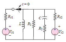
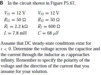
t%3D0 Rs1 R1 R2 Va Vs1 ww 8 In the circuit shown in Figure P5.67, Vsi = 12 V Rsı = 50 2 Vsz = 12 V Rsz = 50 2 R = 2.2 k2 R2 = 600 2 L = 7.8 mH C = 68 µF %3D Assume that DC steady-state conditions exist for t< 0. Determine the voltage across the capacitor and the current through the inductor as t approaches infinity. Remember to specify the polarity of the voltage and the direction of the current that you assume for your solution.
t%3D0 Rs1 R1 R2 Va Vs1 ww 8 In the circuit shown in Figure P5.67, Vsi = 12 V Rsı = 50 2 Vsz = 12 V Rsz = 50 2 R = 2.2 k2 R2 = 600 2 L = 7.8 mH C = 68 µF %3D Assume that DC steady-state conditions exist for t< 0. Determine the voltage across the capacitor and the current through the inductor as t approaches infinity. Remember to specify the polarity of the voltage and the direction of the current that you assume for your solution.

Introductory Circuit Analysis (13th Edition)
13th Edition
ISBN:9780133923605
Author:Robert L. Boylestad
Publisher:Robert L. Boylestad
Chapter1: Introduction
Section: Chapter Questions
Problem 1P: Visit your local library (at school or home) and describe the extent to which it provides literature...

Related questions
Question
Transcribed Image Text:t%3D0
Rs1
R1
R2
Va
Vs1
ww
Transcribed Image Text:8 In the circuit shown in Figure P5.67,
Vsi = 12 V
Rsı = 50 2
Vsz = 12 V
Rsz = 50 2
R = 2.2 k2
R2 = 600 2
L = 7.8 mH
C = 68 µF
%3D
Assume that DC steady-state conditions exist for
t< 0. Determine the voltage across the capacitor and
the current through the inductor as t approaches
infinity. Remember to specify the polarity of the
voltage and the direction of the current that you
assume for your solution.
Expert Solution
Step 1
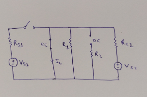
From the circuit diagram, the switch is opened and the circuit is in DC steady-state conditions as t approaches infinity.
It is known that the capacitor behaves as an open circuit and the inductor behaves as the short circuit under steady-state condition.
Redraw the circuit diagram as t approaches infinity,

Step by step
Solved in 2 steps with 3 images

Recommended textbooks for you
Introductory Circuit Analysis (13th Edition)
Electrical Engineering
ISBN:
9780133923605
Author:
Robert L. Boylestad
Publisher:
PEARSON

Delmar's Standard Textbook Of Electricity
Electrical Engineering
ISBN:
9781337900348
Author:
Stephen L. Herman
Publisher:
Cengage Learning

Programmable Logic Controllers
Electrical Engineering
ISBN:
9780073373843
Author:
Frank D. Petruzella
Publisher:
McGraw-Hill Education
Introductory Circuit Analysis (13th Edition)
Electrical Engineering
ISBN:
9780133923605
Author:
Robert L. Boylestad
Publisher:
PEARSON
Delmar's Standard Textbook Of Electricity
Electrical Engineering
ISBN:
9781337900348
Author:
Stephen L. Herman
Publisher:
Cengage Learning
Programmable Logic Controllers
Electrical Engineering
ISBN:
9780073373843
Author:
Frank D. Petruzella
Publisher:
McGraw-Hill Education

Fundamentals of Electric Circuits
Electrical Engineering
ISBN:
9780078028229
Author:
Charles K Alexander, Matthew Sadiku
Publisher:
McGraw-Hill Education

Electric Circuits. (11th Edition)
Electrical Engineering
ISBN:
9780134746968
Author:
James W. Nilsson, Susan Riedel
Publisher:
PEARSON

Engineering Electromagnetics
Electrical Engineering
ISBN:
9780078028151
Author:
Hayt, William H. (william Hart), Jr, BUCK, John A.
Publisher:
Mcgraw-hill Education,