9) Consider the circuit shown in the figure below: For time t0, all capacitors are discharged and the switch is open. At time t-0 the switch is closed Find the steady state (t-> ) DC value of voltages v, v2 and v3 1 kΩ -W to 4 kΩ V3 5F 20V Oksb OMF 3uF :5 kQ w
9) Consider the circuit shown in the figure below: For time t0, all capacitors are discharged and the switch is open. At time t-0 the switch is closed Find the steady state (t-> ) DC value of voltages v, v2 and v3 1 kΩ -W to 4 kΩ V3 5F 20V Oksb OMF 3uF :5 kQ w

Delmar's Standard Textbook Of Electricity
7th Edition
ISBN:9781337900348
Author:Stephen L. Herman
Publisher:Stephen L. Herman
Chapter17: Resistive-inductive Series Circuits
Section: Chapter Questions
Problem 2PP: Assume that the voltage drop across the resistor, ER, is 78 V, that the voltage drop across the...

Related questions

Question
Refer to attached image
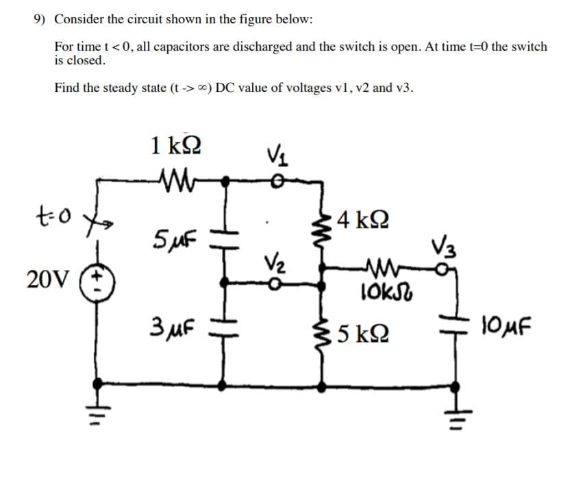
Transcribed Image Text:9) Consider the circuit shown in the figure below:
For time t0, all capacitors are discharged and the switch is open. At time t-0 the switch
is closed
Find the steady state (t-> ) DC value of voltages v, v2 and v3
1 kΩ
-W
to
4 kΩ
V3
5F
20V
Oksb
OMF
3uF
:5 kQ
w
Expert Solution
This question has been solved!
Explore an expertly crafted, step-by-step solution for a thorough understanding of key concepts.

This is a popular solution!

Trending now
This is a popular solution!

Step by step
Solved in 7 steps with 6 images

Knowledge Booster


Learn more about
Need a deep-dive on the concept behind this application? Look no further. Learn more about this topic, electrical-engineering and related others by exploring similar questions and additional content below.Recommended textbooks for you
Delmar's Standard Textbook Of Electricity
Electrical Engineering
ISBN:
9781337900348
Author:
Stephen L. Herman
Publisher:
Cengage Learning
Delmar's Standard Textbook Of Electricity
Electrical Engineering
ISBN:
9781337900348
Author:
Stephen L. Herman
Publisher:
Cengage Learning