- A cantilever truss supports three forces at joints along the top edge, as shown in the figure below. The forces have magnitudes F₁ = 7 kip, F₂ = 6 kip, and F3 = 9 kip. The truss is held in equilibrium by a pin at point A and a roller at point G. The lengths for members DE, EF, and FG is s = 6 ft and for member AG is h = 15 ft. Note that members BF and CE are vertical, and side ABCD is a straight line. The truss members are fabricated from low-carbon steel with a yield strength of Sy = ±32 ksi. Using the method of sections, determine the minimum cross sectional areas for members AB, BF, and EF so that each one exhibits a safety factor of SF = 2.1 with respect to yielding. - Note: Express tension forces as positive (+) and compression forces as negative (-). F₁ h A G S B L F S F₂ C E S F3 D
- A cantilever truss supports three forces at joints along the top edge, as shown in the figure below. The forces have magnitudes F₁ = 7 kip, F₂ = 6 kip, and F3 = 9 kip. The truss is held in equilibrium by a pin at point A and a roller at point G. The lengths for members DE, EF, and FG is s = 6 ft and for member AG is h = 15 ft. Note that members BF and CE are vertical, and side ABCD is a straight line. The truss members are fabricated from low-carbon steel with a yield strength of Sy = ±32 ksi. Using the method of sections, determine the minimum cross sectional areas for members AB, BF, and EF so that each one exhibits a safety factor of SF = 2.1 with respect to yielding. - Note: Express tension forces as positive (+) and compression forces as negative (-). F₁ h A G S B L F S F₂ C E S F3 D

Chapter2: Loads On Structures
Section: Chapter Questions
Problem 1P

Related questions
Question
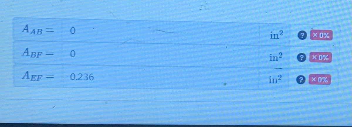
Transcribed Image Text:AAB =
ABF=
AEF=
0
0
0.236
in²
in²
in²
?
X 0%
x 0%
X 0%
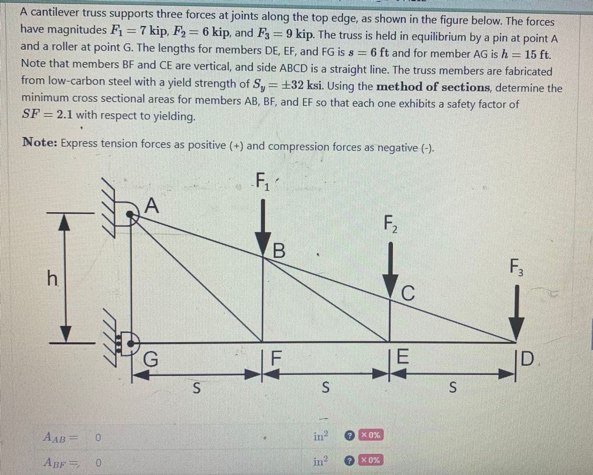
Transcribed Image Text:A cantilever truss supports three forces at joints along the top edge, as shown in the figure below. The forces
have magnitudes F₁ = 7 kip, F₂ = 6 kip, and F3 = 9 kip. The truss is held in equilibrium by a pin at point A
and a roller at point G. The lengths for members DE, EF, and FG is s = 6 ft and for member AG is h = 15 ft.
Note that members BF and CE are vertical, and side ABCD is a straight line. The truss members are fabricated
from low-carbon steel with a yield strength of Sy = ±32 ksi. Using the method of sections, determine the
minimum cross sectional areas for members AB, BF, and EF so that each one exhibits a safety factor of
SF = 2.1 with respect to yielding.
Note: Express tension forces as positive (+) and compression forces as negative (-).
F₁
h
AAB
ABF=
0
0
A
G
S
B
3
S
in²
(?) X0%
F₂
C
E
S
F₁
3
D
Expert Solution
This question has been solved!
Explore an expertly crafted, step-by-step solution for a thorough understanding of key concepts.

This is a popular solution!

Trending now
This is a popular solution!

Step by step
Solved in 4 steps with 3 images

Knowledge Booster


Learn more about
Need a deep-dive on the concept behind this application? Look no further. Learn more about this topic, civil-engineering and related others by exploring similar questions and additional content below.Recommended textbooks for you

Structural Analysis (10th Edition)
Civil Engineering
ISBN:
9780134610672
Author:
Russell C. Hibbeler
Publisher:
PEARSON

Principles of Foundation Engineering (MindTap Cou…
Civil Engineering
ISBN:
9781337705028
Author:
Braja M. Das, Nagaratnam Sivakugan
Publisher:
Cengage Learning
Structural Analysis (10th Edition)
Civil Engineering
ISBN:
9780134610672
Author:
Russell C. Hibbeler
Publisher:
PEARSON
Principles of Foundation Engineering (MindTap Cou…
Civil Engineering
ISBN:
9781337705028
Author:
Braja M. Das, Nagaratnam Sivakugan
Publisher:
Cengage Learning

Fundamentals of Structural Analysis
Civil Engineering
ISBN:
9780073398006
Author:
Kenneth M. Leet Emeritus, Chia-Ming Uang, Joel Lanning
Publisher:
McGraw-Hill Education


Traffic and Highway Engineering
Civil Engineering
ISBN:
9781305156241
Author:
Garber, Nicholas J.
Publisher:
Cengage Learning