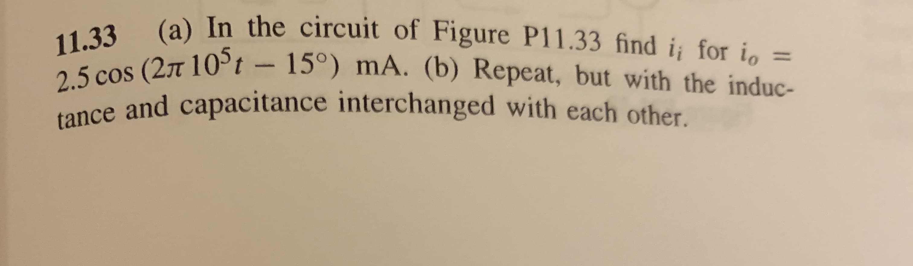
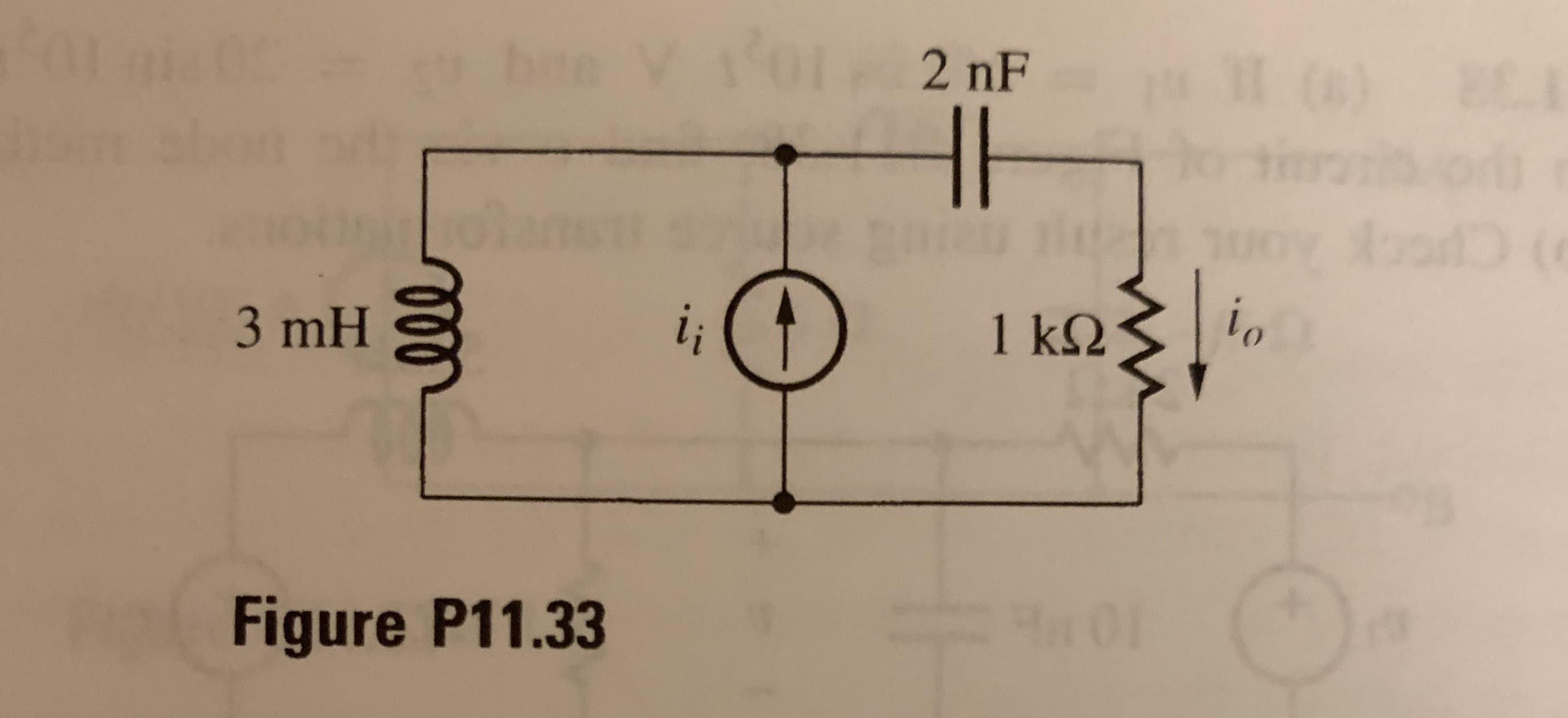
(a) In the circuit of Figure P11.33 find i for i= 11.33 2.5 cos (27t 105t - 15°) mA. (b) Repeat, but with the induc- tance and capacitance interchanged with each other. for HH 6) 2 nF 2 oD i 1 k2 3 mH Figure P11.33


Q: y[(t) = {3e-2t, t0 {0, otherwise The function above defines a voltage signal y(t)…
A:
Q: Q1/ Consider the system with: = 0.65 , wn = 5.3 rad/sec. Let us obtain the rise time t,, peak time…
A: Given data ∈=0.65ωn=5.3 rad/secTo find a) Peak timetp=πωn1-∈tp=π0.51-(0.65)2tp=9.82 sec Overshoot…
Q: Calculate i for t > 0, if ig = 10 A and the circuit is in steady state permanent at t = 0-. how to…
A:
Q: Figure 4(b) is the Miller equivalent circuit of the circuit in Figure 4(a). Derive a relationship…
A: We’ll answer the first question since the exact one wasn’t specified. Please submit a new question…
Q: (c) From Figure Q2(c), calculate the time domain steady state expression for v, i, and iz when is =…
A: To solve above problem, one should have basic idea about working of AC circuits. Above given circuit…
Q: 3. Two magnetically coupled coils are wound on a nonmagnetic core. The self- inductance of coil one…
A: Part (A):- The given magnetically coupled coils are wound on a non-magnetic core. The…
Q: 5. a. Find the mathematical expressions for the transient behavior of the voltage vc and the current…
A:
Q: An electromotive force of 100 volts is applied to an RC series circuit, in which the resistance is…
A:
Q: a- Find the mathematical expression for the transient behavior of Ve. le and Vg for the circuit of…
A:
Q: (c) From Figure Q2(c), calculate the time domain steady state expression for v, i,, and iz when i, =…
A: In this question, Find the current i1 and i2 in time domain Also find the voltage v(t) . We know…
Q: Consider an inductor whose inductance varies as L(x) 0.25H/cm-z, where is the variable length of the…
A:
Q: The RLC circuit below is first running at a constant 240 volts, such that I(0) 4, and I'(0) = 0.…
A:
Q: (c) From Figure Q2(c), calculate the time domain steady state expression for v, i,, and iz when i, =…
A:
Q: Ex. 177. Given R= E= 3 volts DC source, and a switch - all in series. 7 Ohms, C= 6 Farads, The…
A:
Q: Find the average power delivered to the 20 Ω resistor.
A: To find the power delivered to the 20 ohm resistor. First, use the source transformation of the 5A…
Q: Ex. 170. Given R= 16 Ohms, C= 14 Farads, Henries, V= 11 volts DC, and a switch The switch closes at…
A:
Q: Ex: For the circuit shown in the figure below: 1. Find the mathematical expression for the transient…
A: Note: We are authorized to answer three subparts at a time since you have not mentioned which part…
Q: Q1/ Consider the system with: } = 0.65 , wn = 5.3 rad/sec. Let us obtain the rise time tr , peak…
A:
Q: Consider an LRC series circuit with a resistance of 2.5 ohms, capacitance of 0.1 farad, an…
A:
Q: 1. A circuit consist of an inductance of 0.50 henry, a resistance of 20 ohms, a condenser of…
A:
Q: Q1. For the system shown in Figure (1) E. R(a) C( K₁ 2+1 D(a) Figure (1) Design the values of K, and…
A: A block diagram of closed-loop control system is given in the question. The steady state error due…
Q: (a) For the circuit shown in Figure Q5.1 determine the angular frequency of the sinusoidal supply…
A: a) find the angular frequency of the supply voltage in order to maximize the active Power…
Q: Figure 4(b) is the Miller equivalent circuit of the circuit in Figure 4(a). Derive a relationship…
A: “Since you have asked multiple question, we will solve the first question for you. If you want any…
Q: The current io(0+) in A and the energy stored in the capacitor at t=(0+) in j and the current ic(t)…
A: According to question: a) Before t=0, steady state has reached so capacitor will behave as open…
Q: A= 900 hr/failure, MT13 F of Component 13 Q) In the e lectrical circuit shown, all component are…
A: Resistors, inductors and capacitors form an integral part of any electrical circuit. A source,…
Q: Derive the voltage waveform as v(z, 1) = |V cos(@t - B: +6+)e a: + |Vcos(@t + B: +0)ez 2.9 Where We…
A:
Q: From Figure Q2(c), calculate the time domain steady state expression for v, i,, and iz when i, = 10…
A:
Q: A possible solution for a first and second order derivatives have the same form expressed as a. At?…
A:
Q: A current source, IS =11.9cos(2800t) A, a resistor R=289Ω, and an inductor, L=0.44 H are all in…
A: The circuit of the parallel-connected resistor and inductor with current source is shown below, IS…
Q: a. Assuming that the circuit is balanced, that is, that Vab = 0, determine X4 in terms of the…
A: In a Wheatstone bridge, It contains four pure resistive branch R1, R2, R3 and R4. To identify the…
Q: A current source, I, = 12.1 cos(2500t) A, a resistor R = 2102, and an inductor, L = 0.26 H are all…
A: The inductive reactance of the inductor is Substitute the given values.
Q: The source voltage is Vs = 48.59 sin 90° in the following circuit having R1= 48.59 k2 series…
A:
Q: Derive Time-domain Specifications ( Delay Time, Rise Time, Settling time, Percentage overshoot) of…
A:
Q: Homework: For the circuit shown in the figure below: 1. Find the mathematical expression for the…
A: Given:-
Q: In the following circuit, the voltage source is supplying Vde = 39.79 V. The switch S remains close…
A:
Q: «Investigation of the transient process in the first order RC and RL circuits» 1. Preliminary…
A: *Keeping a note ?as per our company guidelines we are supposed to answer ?️only first 3️⃣ sub-parts.…
Q: Q.6: For the circuit shown beside, the switch in position "1" for long period enough for…
A:
Q: "he initial values of ij and iz in the circuit shown in Figure Q1(b) are +3A and -5A cspectively.…
A:
Q: E5.18 A system is shown in Figure E5.18(a). The response to a unit step, when K=1, is shown in…
A: The given system is shown below: The transfer function of the above system is,…
Q: Calculate i for t > 0, if ig = 10 A and the circuit is in steady state permanent at t = 0-.
A:
Q: a. Describe the behavior of the capacitor's voltage: (i) initial and final steady states, (ii)…
A: In this question, We need to determine the voltage across the capacitor? Explain the behavior of…
Q: 4.b 1- Draw the SFG diagram 2- When 8u(t) is applied as input, enter the steady-state value of the…
A: According to the question, (1) We need to draw the SFG for the given block diagram as shown below…
Q: Homework: For the circuit shown in the figure below: 1. Find the mathematical expression for the…
A: The circuit is as shown below :
Q: Q1/ Consider the system with: = 0.65, Wn = 5.3 rad/sec. Let us obtain the rise time ty , peak time…
A:
Q: (c) From Figure Q2(c), calculate the time domain steady state expression for v, i1, and iz when is =…
A:


Trending now
This is a popular solution!

Step by step
Solved in 10 steps with 10 images

- a) Find the final value for the capacitor voltage (Vc(∞ ))? b) Find the circuit time constant for t>0? c) Find an expression for the capcitor voltage for t>0?Ex : For the circuit shown in the figure below : 1. Find the mathematical expression for the transient behaviour of the voltage across the capacitor as well as the current of the capacitor if the capacitor was initially uncharged and the switch is closed at position 1 when t - o sec . 2. Find the mathematical expression for Vc and is if the switch is moved to position 2 at t = 10msec . 3. Find the mathematical expressions for Vc and ic if the switch is moved to position 3 at t = 20msec 4. Plot the waveforms of the Vc and is obtained from the parts 1 to 3 . R ic 20 kΩ 20 E 12 V C 0.05 uF vc R , 310 ΚΩ TA resistor, an inductor, and a capacitor are connected in parallel to an ac source with voltage amplitude V and angular frequency v. Let the source voltage be given by v = Vcosvt. (a) Show that each of the instantaneous voltages vR, vL, and vC at any instant is equal to v and that i = iR + iL + iC, where i is the current through the source and iR, iL, and iC are the currents through the resistor, inductor, and capacitor, respectively. (b) What are the phases of iR, iL, and iC with respect to v? Use current phasors to represent i, iR, iL, and iC. In a phasor diagram, show the phases of these four currents with respect to v. (c) Use the phasor diagram of part (b) to show that the current amplitude I for the current i through the source is I = √(I2R) + (IC - IL)2 . (d) Show that the result of part (c) can be written as I = V/Z, with 1/Z = √ (1/R2) + [ωC - (1/ωL)]2.
- a) What is the time domain expression for the current? b) If the load impendance is created by an inductor with value L=375 mH, find the phaser voltage Vx? c) If the load impendance is created by a capacitor with value C=16.7 uF, find the phaser voltage Vx?The pathway for a binary electrical signal between gates in an integrated circuit can be modeled as an RC circuit, as shown in the figure to the right; the voltage source models the transmitting gate, and the capacitor models the receiving gate. Suppose the resistance is 500 ohms and the capacitance is 10^-12 F (1 picofarad, pF. If the capacitor is initially uncharged and the transmitting gate changes instantaneously from 0 to 6 V, how long will it take for the voltage at the receiving gate to reach 5 V?By Differential equations An electromotive force of 100 volts is applied to an RC series circuit, in which the resistance is 50 ohms and the capacitance is 0.002 farads. Determine the load q(t) of the capacitor, if q(0) = 5C. Find the current i(t). Pls dont skip any steps even on the integrals
- Q5. For an exhibition project you are designing a circuit of signal processor which can be connected to 230V, 50 Hz supply have a 5.0 H inductor, 80 μ F capacitor and 40Ω resistor kept in series. How can you evaluate the rms current and average power delivered to the circuit? Based on your observation, evaluate the potential drop across capacitance and inductor. Comment about that r m s voltage found in this circuit is less than peak voltage? Justify it with your answer. If you remove the inductor and connect a bulb in series with a capacitor. What will happen to the brightness of bulb if it is connected to DC source and then to an AC source. Assess and find reason for your observations in each case.What are two real-world consequences of having to amplify the input to a system so that the output reaches a desired steady-state value? Related to Electroncis & CircuitsLet Vs=530tᶾ v, leg t >0 and iL (0) = 1 A, in the circuit shown, at t=0.2s, determine the values of the energy stored in the capacitor and the coil. The circuit is in the attached image.
- Describe the steady-state similarities and differences of DC and AC circuits with purelyresistive elementsa. Find the mathematical expressions for the transient behavior of thevoltage vC and the current iC if the capacitor was initially unchargedand the switch is thrown into position 1 at t = 0 s.b. Find the mathematical expressions for the voltage vC and the current iCif the switch is moved to position 2 at t = 3 ms.c. Find the mathematical expressions for the voltage vC and the current if theswitch is thrown into position 3 at t =5 ms.d. Plot the waveforms obtained in parts (a)–(c)A circuit is designed with an AC source of max voltage 12 and frequency 60 Hz. The circuit has a resistance of 1050 Ohms, an inductance of 0.06 Henrys, and a capacitance of 0.009 coulombs per volt. - omega for source in rad/s? - omegaR for circuit? -XL? -XC? -phi in radians? -Z? -imax?