Calculate the RC time constant of the circuit in Fig. 1 using equation (1). 1. Part B Derive V oult) expressions for the circuits in Figs. 1 and 2 using the square wave voltage source as specified in Step 4 of Part A (Vin shown below) in regions 1 and 2 (one period of the square wave). Assume V.--0.5V at t 0s. 2. 0.1 uf Laboratory Procedure Part A 10 kΩ ka V Vin 10 kΩ +0.5 V Region 1 0 Region 2 Fig. 2. RC circuit. 0.5 V 1. Repeat steps 4-6 from part A for this circuit for a Vin frequency equal to 100 Hz, but measure the voltage across the resistor instead of the capacitor 3. Sketch your derived results for Vour(t), clearly labeling your initial voltages and time constants for t < 0s, t = 0s, and t > 0 up to the end ofregion 2 (one period of the square wave). *For measuring the time constant, observe the time it takes for the voltage drop across the resistor to go to 37% of its initial value. Fig. 1. RC circuit . Build the circuit on the ELVIS breadboard using a resistance box for the resistor Laboratory Report . Change the resistor value from 10 k92 to 100 k32, and change the frequency to 10 Hz. Observe
Calculate the RC time constant of the circuit in Fig. 1 using equation (1). 1. Part B Derive V oult) expressions for the circuits in Figs. 1 and 2 using the square wave voltage source as specified in Step 4 of Part A (Vin shown below) in regions 1 and 2 (one period of the square wave). Assume V.--0.5V at t 0s. 2. 0.1 uf Laboratory Procedure Part A 10 kΩ ka V Vin 10 kΩ +0.5 V Region 1 0 Region 2 Fig. 2. RC circuit. 0.5 V 1. Repeat steps 4-6 from part A for this circuit for a Vin frequency equal to 100 Hz, but measure the voltage across the resistor instead of the capacitor 3. Sketch your derived results for Vour(t), clearly labeling your initial voltages and time constants for t < 0s, t = 0s, and t > 0 up to the end ofregion 2 (one period of the square wave). *For measuring the time constant, observe the time it takes for the voltage drop across the resistor to go to 37% of its initial value. Fig. 1. RC circuit . Build the circuit on the ELVIS breadboard using a resistance box for the resistor Laboratory Report . Change the resistor value from 10 k92 to 100 k32, and change the frequency to 10 Hz. Observe

Introductory Circuit Analysis (13th Edition)
13th Edition
ISBN:9780133923605
Author:Robert L. Boylestad
Publisher:Robert L. Boylestad
Chapter1: Introduction
Section: Chapter Questions
Problem 1P: Visit your local library (at school or home) and describe the extent to which it provides literature...

Related questions
Question
100%
Can someone help me with question 2 please?
Derive Vout(t) expression for the circuit in figure 1 and figure 2 using the square wave voltage source as specific in Step 4 of part A (Vin shown below) in region 1 and region 2 (one period of the square wave). Assume Vc = -0.5 V at t=0s
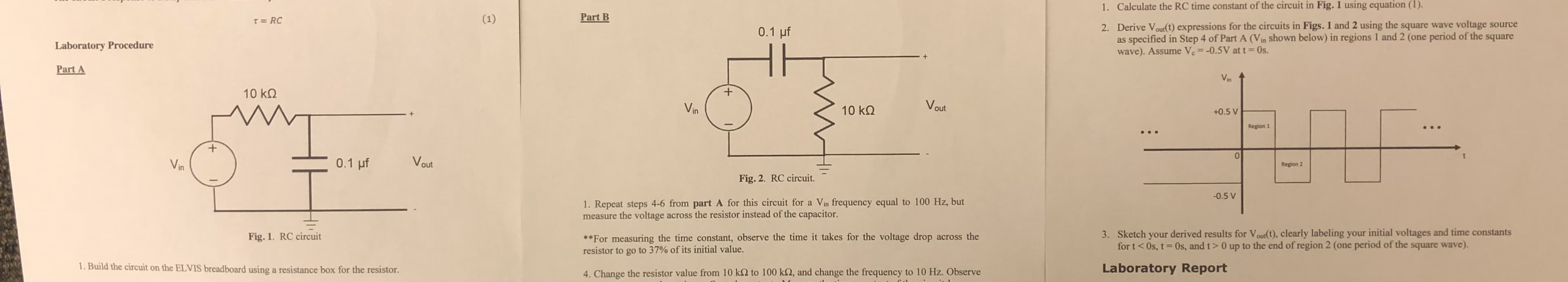
Transcribed Image Text:Calculate the RC time constant of the circuit in Fig. 1 using equation (1).
1.
Part B
Derive V oult) expressions for the circuits in Figs. 1 and 2 using the square wave voltage source
as specified in Step 4 of Part A (Vin shown below) in regions 1 and 2 (one period of the square
wave). Assume V.--0.5V at t 0s.
2.
0.1 uf
Laboratory Procedure
Part A
10 kΩ
ka V
Vin
10 kΩ
+0.5 V
Region 1
0
Region 2
Fig. 2. RC circuit.
0.5 V
1. Repeat steps 4-6 from part A for this circuit for a Vin frequency equal to 100 Hz, but
measure the voltage across the resistor instead of the capacitor
3. Sketch your derived results for Vour(t), clearly labeling your initial voltages and time constants
for t < 0s, t = 0s, and t > 0 up to the end ofregion 2 (one period of the square wave).
*For measuring the time constant, observe the time it takes for the voltage drop across the
resistor to go to 37% of its initial value.
Fig. 1. RC circuit
. Build the circuit on the ELVIS breadboard using a resistance box for the resistor
Laboratory Report
. Change the resistor value from 10 k92 to 100 k32, and change the frequency to 10 Hz. Observe
Expert Solution


Trending now
This is a popular solution!

Step by step
Solved in 10 steps with 10 images

Knowledge Booster


Learn more about
Need a deep-dive on the concept behind this application? Look no further. Learn more about this topic, electrical-engineering and related others by exploring similar questions and additional content below.Recommended textbooks for you
Introductory Circuit Analysis (13th Edition)
Electrical Engineering
ISBN:
9780133923605
Author:
Robert L. Boylestad
Publisher:
PEARSON

Delmar's Standard Textbook Of Electricity
Electrical Engineering
ISBN:
9781337900348
Author:
Stephen L. Herman
Publisher:
Cengage Learning

Programmable Logic Controllers
Electrical Engineering
ISBN:
9780073373843
Author:
Frank D. Petruzella
Publisher:
McGraw-Hill Education
Introductory Circuit Analysis (13th Edition)
Electrical Engineering
ISBN:
9780133923605
Author:
Robert L. Boylestad
Publisher:
PEARSON
Delmar's Standard Textbook Of Electricity
Electrical Engineering
ISBN:
9781337900348
Author:
Stephen L. Herman
Publisher:
Cengage Learning
Programmable Logic Controllers
Electrical Engineering
ISBN:
9780073373843
Author:
Frank D. Petruzella
Publisher:
McGraw-Hill Education

Fundamentals of Electric Circuits
Electrical Engineering
ISBN:
9780078028229
Author:
Charles K Alexander, Matthew Sadiku
Publisher:
McGraw-Hill Education

Electric Circuits. (11th Edition)
Electrical Engineering
ISBN:
9780134746968
Author:
James W. Nilsson, Susan Riedel
Publisher:
PEARSON

Engineering Electromagnetics
Electrical Engineering
ISBN:
9780078028151
Author:
Hayt, William H. (william Hart), Jr, BUCK, John A.
Publisher:
Mcgraw-hill Education,