T.7 A system for controlling flow is shown in Fig.T.7 Increasing the desired flow setting increases the compression on spring K₁, which causes z and position e of the balanced valve to move up. This in turn causes the flow valve to move down, which increases the flow. The amount of flow out is measured by a venturi-type flowmeter so that the pressure drop P₁ P, is a function of Q.. The diaphragm pre- vents leakage from the high pressure P₁ to the low pressure P₁, but it permits motion, just as a piston would. The effective area of the diaphragm is A4. The flow Q. is seen - to be a function of the flow-valve opening Y and the supply pressure P. Determine the over-all block-diagram representation for this system.
T.7 A system for controlling flow is shown in Fig.T.7 Increasing the desired flow setting increases the compression on spring K₁, which causes z and position e of the balanced valve to move up. This in turn causes the flow valve to move down, which increases the flow. The amount of flow out is measured by a venturi-type flowmeter so that the pressure drop P₁ P, is a function of Q.. The diaphragm pre- vents leakage from the high pressure P₁ to the low pressure P₁, but it permits motion, just as a piston would. The effective area of the diaphragm is A4. The flow Q. is seen - to be a function of the flow-valve opening Y and the supply pressure P. Determine the over-all block-diagram representation for this system.

Elements Of Electromagnetics
7th Edition
ISBN:9780190698614
Author:Sadiku, Matthew N. O.
Publisher:Sadiku, Matthew N. O.
ChapterMA: Math Assessment
Section: Chapter Questions
Problem 1.1MA

Related questions

Question
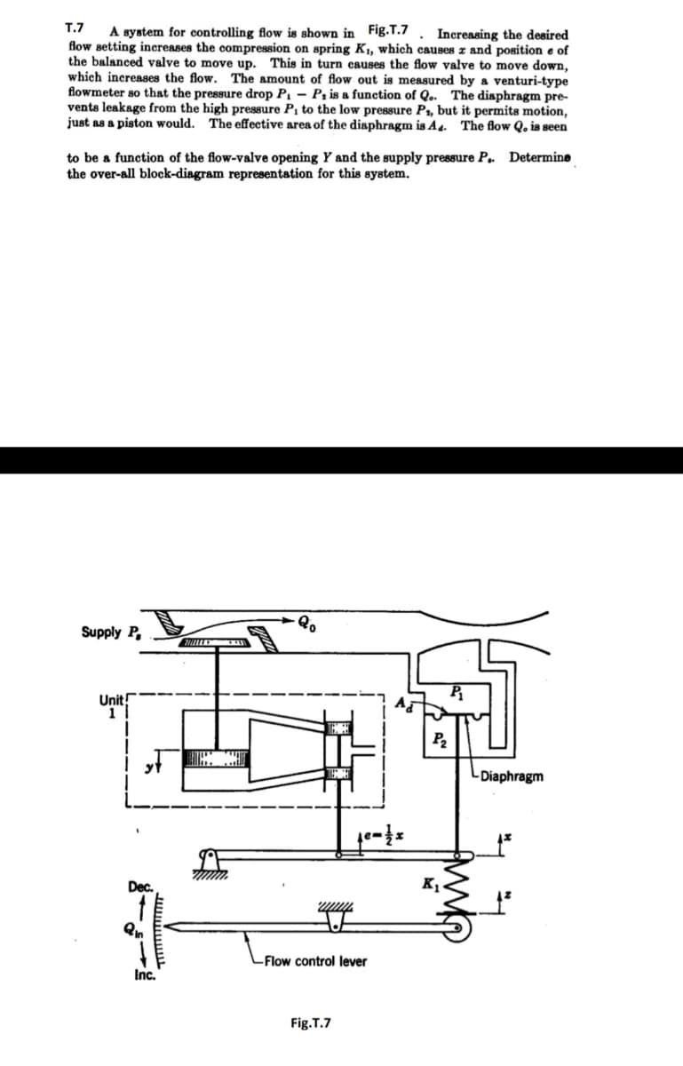
Transcribed Image Text:T.7 A system for controlling flow is shown in Fig.T.7
Increasing the desired
flow setting increases the compression on spring K₁1, which causes z and position e of
the balanced valve to move up. This in turn causes the flow valve to move down,
which increases the flow. The amount of flow out is measured by a venturi-type
flowmeter so that the pressure drop P₁ - P, is a function of Q.. The diaphragm pre-
vents leakage from the high pressure P₁ to the low pressure P₁, but it permits motion,
just as a piston would. The effective area of the diaphragm is A4. The flow Q. is seen
to be a function of the flow-valve opening Y and the supply pressure P.. Determine
the over-all block-diagram representation for this system.
Supply P,
Unit!
1
Dec.
Qn
Inc.
www.
Qo
wwww.
-Flow control lever
Fig.T.7
P₂
K₁
-Diaphragm
Expert Solution
This question has been solved!
Explore an expertly crafted, step-by-step solution for a thorough understanding of key concepts.

Step by step
Solved in 2 steps with 1 images

Follow-up Questions
Read through expert solutions to related follow-up questions below.
Follow-up Question
Can you provide a full solution, with the equations?
Solution
Knowledge Booster


Learn more about
Need a deep-dive on the concept behind this application? Look no further. Learn more about this topic, mechanical-engineering and related others by exploring similar questions and additional content below.Recommended textbooks for you
Elements Of Electromagnetics
Mechanical Engineering
ISBN:
9780190698614
Author:
Sadiku, Matthew N. O.
Publisher:
Oxford University Press

Mechanics of Materials (10th Edition)
Mechanical Engineering
ISBN:
9780134319650
Author:
Russell C. Hibbeler
Publisher:
PEARSON

Thermodynamics: An Engineering Approach
Mechanical Engineering
ISBN:
9781259822674
Author:
Yunus A. Cengel Dr., Michael A. Boles
Publisher:
McGraw-Hill Education
Elements Of Electromagnetics
Mechanical Engineering
ISBN:
9780190698614
Author:
Sadiku, Matthew N. O.
Publisher:
Oxford University Press
Mechanics of Materials (10th Edition)
Mechanical Engineering
ISBN:
9780134319650
Author:
Russell C. Hibbeler
Publisher:
PEARSON
Thermodynamics: An Engineering Approach
Mechanical Engineering
ISBN:
9781259822674
Author:
Yunus A. Cengel Dr., Michael A. Boles
Publisher:
McGraw-Hill Education

Control Systems Engineering
Mechanical Engineering
ISBN:
9781118170519
Author:
Norman S. Nise
Publisher:
WILEY

Mechanics of Materials (MindTap Course List)
Mechanical Engineering
ISBN:
9781337093347
Author:
Barry J. Goodno, James M. Gere
Publisher:
Cengage Learning

Engineering Mechanics: Statics
Mechanical Engineering
ISBN:
9781118807330
Author:
James L. Meriam, L. G. Kraige, J. N. Bolton
Publisher:
WILEY