Circuit olrig. f'ce oltage Vs(1)! .45 M-p1ase withi lfe su (1)sa b 4 mH 108.33 iF i(t) 50 Ω Figure P7.47: Circuit for Problem 7.47 Ds(t) 0.2 H 0.2 mF 7.48 Determine the Thévenin equivalent of the circuit in Fig. P7.48 at terminals (a, b), given that b 0.2 mF Us(t)12 cos 2500t V Figure P7.45: Circuit for Problem 7.45 0.5 cos(2500r - 30°) A. is(t) 450 CHAPTER 7 AC ANALYSIS 2 kΩ 3 k2 5 Q W | IL 4 mH 4 mH 15/0 V j6 k ZL )Us(t) is) :80 μF 10Ω b Figure P7.51: Circuit for Problem 7.51 Figure P7.48: Circuit for Problem 7.48. Sections 7-7 and 7-8: Phasor Diagrams and Phase Shifters 000
Circuit olrig. f'ce oltage Vs(1)! .45 M-p1ase withi lfe su (1)sa b 4 mH 108.33 iF i(t) 50 Ω Figure P7.47: Circuit for Problem 7.47 Ds(t) 0.2 H 0.2 mF 7.48 Determine the Thévenin equivalent of the circuit in Fig. P7.48 at terminals (a, b), given that b 0.2 mF Us(t)12 cos 2500t V Figure P7.45: Circuit for Problem 7.45 0.5 cos(2500r - 30°) A. is(t) 450 CHAPTER 7 AC ANALYSIS 2 kΩ 3 k2 5 Q W | IL 4 mH 4 mH 15/0 V j6 k ZL )Us(t) is) :80 μF 10Ω b Figure P7.51: Circuit for Problem 7.51 Figure P7.48: Circuit for Problem 7.48. Sections 7-7 and 7-8: Phasor Diagrams and Phase Shifters 000

Power System Analysis and Design (MindTap Course List)
6th Edition
ISBN:9781305632134
Author:J. Duncan Glover, Thomas Overbye, Mulukutla S. Sarma
Publisher:J. Duncan Glover, Thomas Overbye, Mulukutla S. Sarma
Chapter6: Power Flows
Section: Chapter Questions
Problem 6.15P

Related questions
Question
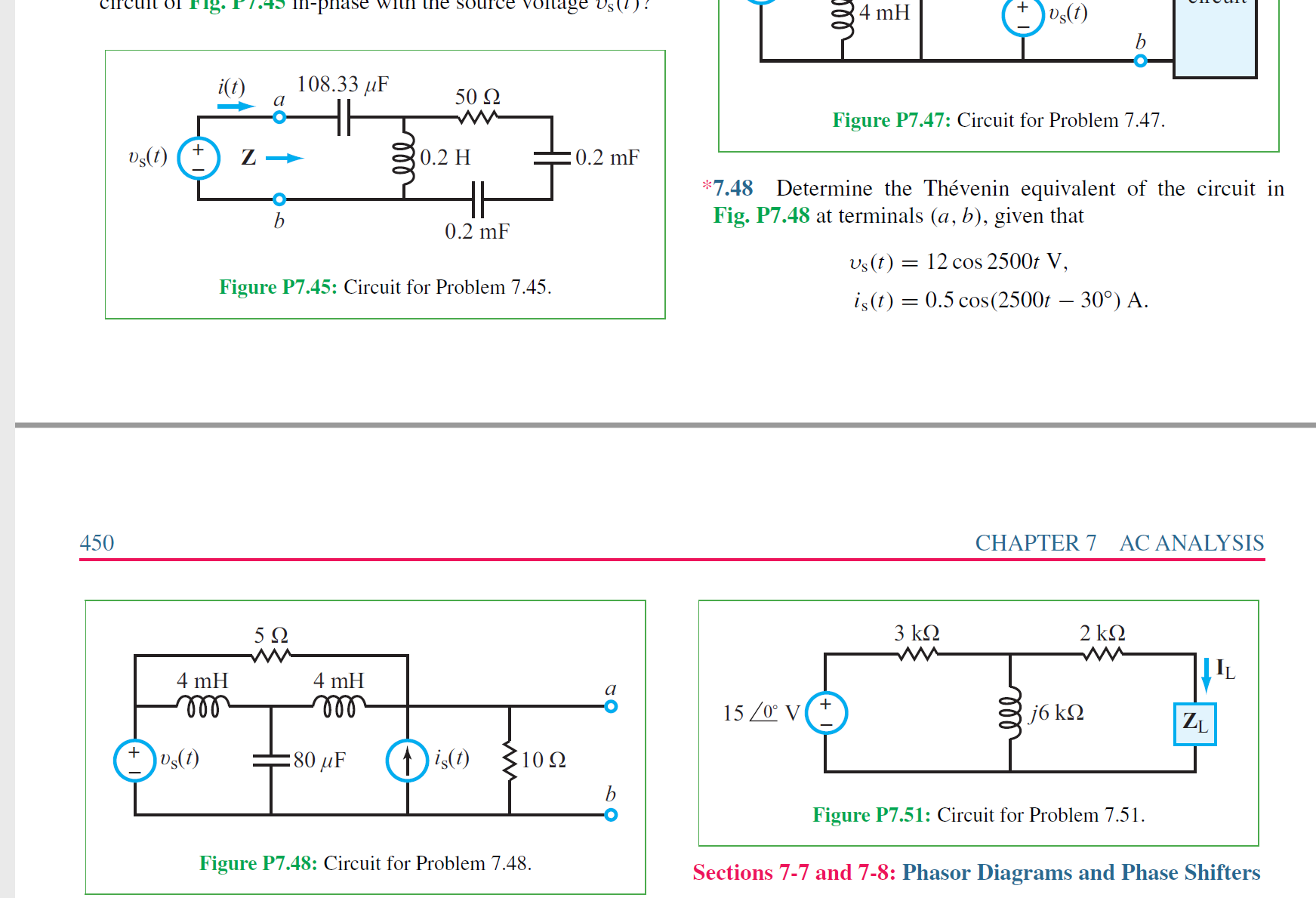
Determine the Th´evenin equivalent of the circuit in
Fig. P7.48 at terminals (a, b), given that
υs(t) = 12 cos 2500t V,
is(t) = 0.5 cos(2500t − 30◦
) A.
Transcribed Image Text:Circuit olrig.
f'ce
oltage Vs(1)!
.45 M-p1ase withi lfe su
(1)sa
b
4 mH
108.33 iF
i(t)
50 Ω
Figure P7.47: Circuit for Problem 7.47
Ds(t)
0.2 H
0.2 mF
7.48 Determine the Thévenin equivalent of the circuit in
Fig. P7.48 at terminals (a, b), given that
b
0.2 mF
Us(t)12 cos 2500t V
Figure P7.45: Circuit for Problem 7.45
0.5 cos(2500r - 30°) A.
is(t)
450
CHAPTER 7
AC ANALYSIS
2 kΩ
3 k2
5 Q
W
| IL
4 mH
4 mH
15/0 V
j6 k
ZL
)Us(t)
is)
:80 μF
10Ω
b
Figure P7.51: Circuit for Problem 7.51
Figure P7.48: Circuit for Problem 7.48.
Sections 7-7 and 7-8: Phasor Diagrams and Phase Shifters
000
Expert Solution


Trending now
This is a popular solution!

Step by step
Solved in 10 steps with 10 images

Knowledge Booster


Learn more about
Need a deep-dive on the concept behind this application? Look no further. Learn more about this topic, electrical-engineering and related others by exploring similar questions and additional content below.Recommended textbooks for you
Power System Analysis and Design (MindTap Course …
Electrical Engineering
ISBN:
9781305632134
Author:
J. Duncan Glover, Thomas Overbye, Mulukutla S. Sarma
Publisher:
Cengage Learning
Power System Analysis and Design (MindTap Course …
Electrical Engineering
ISBN:
9781305632134
Author:
J. Duncan Glover, Thomas Overbye, Mulukutla S. Sarma
Publisher:
Cengage Learning