Date Name Industry Print Exercise 10-1 Refer to the print PR 10-1 and answer the questions below. 1. Note 3 in the upper-left area of the drawing is referring to the crosshatched area on the front view. What is the maximum material condition of the hole in the middle of that area? 2. Where on the drawing is the tolerance specified for the R.50 and the 2X R.12 dimensions and ho much is this tolerance? 3. How many dimensions on this print are expressed with the limit method? 4. This drawing shows a fastener inserted into a hole, as indicated by note 5 in the top view. What is the maximum material condition of that pin? (Note: the front view indicates the size of the hole.) 5. With reference to question 4, the hole in the part is to be .451-.453. What is the allowance for the pin and the hole? 6. Two of the dimensions, 3.165 and 2.114, have boxes around them. As discussed in this unit, what are those dimensions called? 7. Note 1 indicates 10 GAGE 1010-1020 sheet metal can be used to make the main body of this part According to the left side view, how much tolerance is given to the thickness of the metal? 8. The boxes that indicate an A or a B are called identification symbols. 9. The top view shows a bend radius of the thin metal. Would a bend radius of 1/8" meet the requirements? Review questions based on previous units: 10. What paper size is the original version of this print? any section views shown on this print? 11. Are there 12. What is the name of this part? 13. What is the part number of this print? 14. How many chamfered edges are noted by leader lines on this drawing? Which system for placing dimension values is used, aligned or unidirectional? 15 Inc. 10 12 NOTES CHANGES 1. 10 GAGE 1010-1020 HR P&O ZINC YELLOW DI CHROMATE. .190 MAX TO BE CHECKED WITH GO/NO-GO PLUG GAGES. 2 170 R .130 1.0 3 AREAS INDICATED TO BE FREE OF BURRS AND BREAKOUT - SHAVE. CHANGES OHIO FASTENER #RH2708 5/16-18, BEE LIETZE INDUSTRIES ACC-51119 WELD PIN FLANGED PROJECT I ON WELD NUT OR EQUI VALENT. .515 .485 5 CRITICAL FEATURE RANK I NG PER HYDRO-GEAR FMEA PROCESS #602 6 450 .442 453 451 THRU 2.114 .020 A B .971 .931 .600 R 0.560 -C- Ø. 33 + R 520 .480 CHANGES .520 R .480 ø.45 x 45 CHAMFER R 20 . 10 3.165 2PL 2X R. 12 2.120 2.080 1.80 1.40 -R. 50 1.65 -В- 1.25 2 3 893 .887 0.840 R 0.810 -B- .138 .130 2.12- .100 .060 2.770 2.730 .040 4.960 4.920 -.015 WITHIN 1. 65 1-DEAS DRAWING INTERPRETATION TOLERANCES UNLESS SPECIFIED 0.0 .00 .000 .0000 ANGLE -A- PER ASME Y14.5M t.020 t.010 t.005 t.0005 ±1 Hydro-Gear 1411 SO. HAMILTON ST. SULLIVAN, IL 61951 PHONE (217) 728-2581 DATE 08/04 NAME DRAWN CHECKED APPR NAME ARM, RETURN P6 KJR FORMER PART NO. DRAWN IN INCHES X1287-3 SHEET 1 OF 1 PART NO. 51127 SIZE SCALE MATERIAL: SEE NOTES FULL С CHIG P7 FINISH: SEE NOTES PROJECT REFERENCE : 310-3000 12 10 11 Unit 10 Tolerancing 211 Print supplied by Hydro-Gear. PR 10-1. Return Arm.
Date Name Industry Print Exercise 10-1 Refer to the print PR 10-1 and answer the questions below. 1. Note 3 in the upper-left area of the drawing is referring to the crosshatched area on the front view. What is the maximum material condition of the hole in the middle of that area? 2. Where on the drawing is the tolerance specified for the R.50 and the 2X R.12 dimensions and ho much is this tolerance? 3. How many dimensions on this print are expressed with the limit method? 4. This drawing shows a fastener inserted into a hole, as indicated by note 5 in the top view. What is the maximum material condition of that pin? (Note: the front view indicates the size of the hole.) 5. With reference to question 4, the hole in the part is to be .451-.453. What is the allowance for the pin and the hole? 6. Two of the dimensions, 3.165 and 2.114, have boxes around them. As discussed in this unit, what are those dimensions called? 7. Note 1 indicates 10 GAGE 1010-1020 sheet metal can be used to make the main body of this part According to the left side view, how much tolerance is given to the thickness of the metal? 8. The boxes that indicate an A or a B are called identification symbols. 9. The top view shows a bend radius of the thin metal. Would a bend radius of 1/8" meet the requirements? Review questions based on previous units: 10. What paper size is the original version of this print? any section views shown on this print? 11. Are there 12. What is the name of this part? 13. What is the part number of this print? 14. How many chamfered edges are noted by leader lines on this drawing? Which system for placing dimension values is used, aligned or unidirectional? 15 Inc. 10 12 NOTES CHANGES 1. 10 GAGE 1010-1020 HR P&O ZINC YELLOW DI CHROMATE. .190 MAX TO BE CHECKED WITH GO/NO-GO PLUG GAGES. 2 170 R .130 1.0 3 AREAS INDICATED TO BE FREE OF BURRS AND BREAKOUT - SHAVE. CHANGES OHIO FASTENER #RH2708 5/16-18, BEE LIETZE INDUSTRIES ACC-51119 WELD PIN FLANGED PROJECT I ON WELD NUT OR EQUI VALENT. .515 .485 5 CRITICAL FEATURE RANK I NG PER HYDRO-GEAR FMEA PROCESS #602 6 450 .442 453 451 THRU 2.114 .020 A B .971 .931 .600 R 0.560 -C- Ø. 33 + R 520 .480 CHANGES .520 R .480 ø.45 x 45 CHAMFER R 20 . 10 3.165 2PL 2X R. 12 2.120 2.080 1.80 1.40 -R. 50 1.65 -В- 1.25 2 3 893 .887 0.840 R 0.810 -B- .138 .130 2.12- .100 .060 2.770 2.730 .040 4.960 4.920 -.015 WITHIN 1. 65 1-DEAS DRAWING INTERPRETATION TOLERANCES UNLESS SPECIFIED 0.0 .00 .000 .0000 ANGLE -A- PER ASME Y14.5M t.020 t.010 t.005 t.0005 ±1 Hydro-Gear 1411 SO. HAMILTON ST. SULLIVAN, IL 61951 PHONE (217) 728-2581 DATE 08/04 NAME DRAWN CHECKED APPR NAME ARM, RETURN P6 KJR FORMER PART NO. DRAWN IN INCHES X1287-3 SHEET 1 OF 1 PART NO. 51127 SIZE SCALE MATERIAL: SEE NOTES FULL С CHIG P7 FINISH: SEE NOTES PROJECT REFERENCE : 310-3000 12 10 11 Unit 10 Tolerancing 211 Print supplied by Hydro-Gear. PR 10-1. Return Arm.

Elements Of Electromagnetics
7th Edition
ISBN:9780190698614
Author:Sadiku, Matthew N. O.
Publisher:Sadiku, Matthew N. O.
ChapterMA: Math Assessment
Section: Chapter Questions
Problem 1.1MA

Related questions

Question
I need the answer for problem number 14.
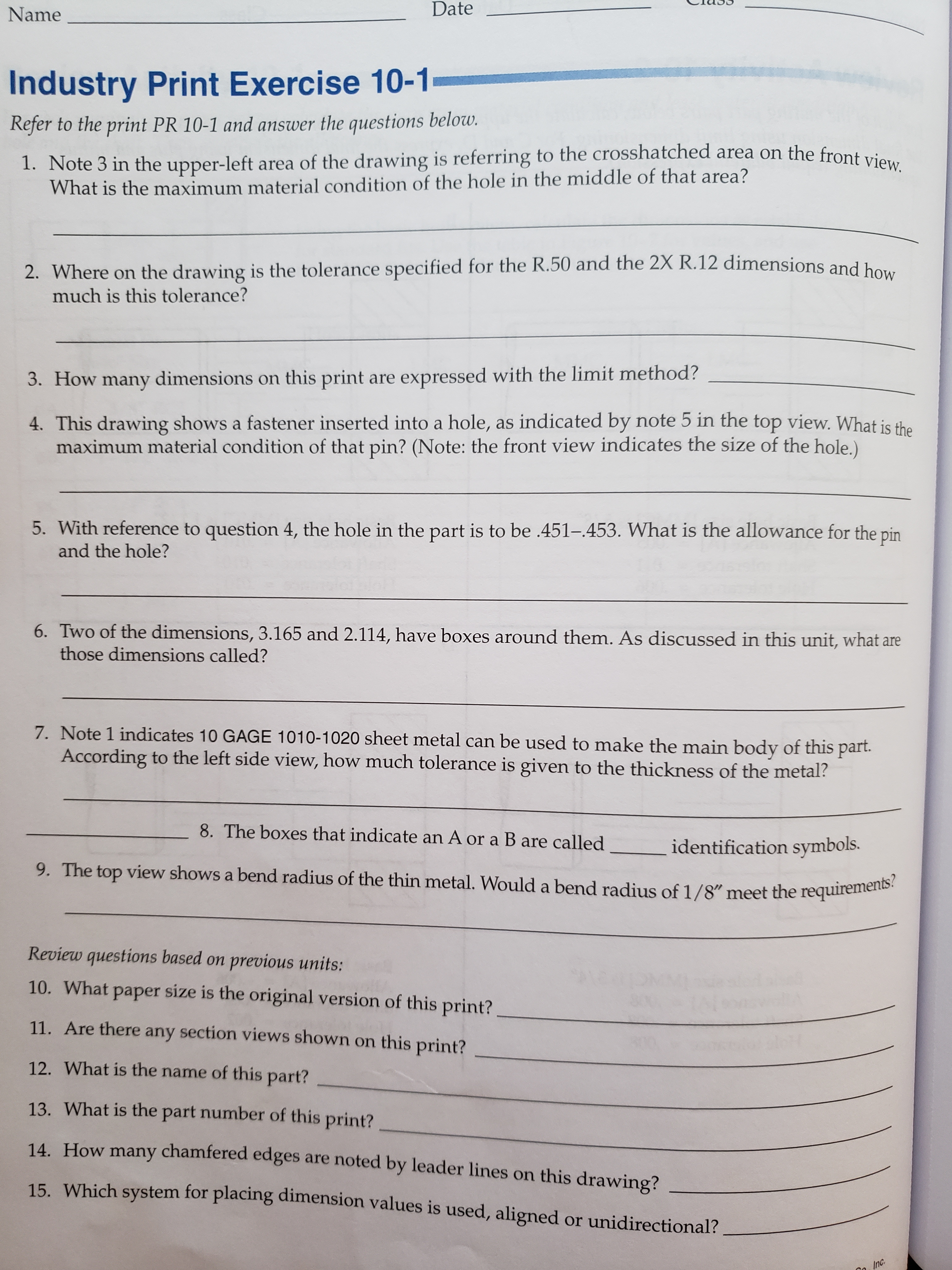
Transcribed Image Text:Date
Name
Industry Print Exercise 10-1
Refer to the print PR 10-1 and answer the questions below.
1. Note 3 in the upper-left area of the drawing is referring to the crosshatched area on the front view.
What is the maximum material condition of the hole in the middle of that area?
2. Where on the drawing is the tolerance specified for the R.50 and the 2X R.12 dimensions and ho
much is this tolerance?
3. How many dimensions on this print are expressed with the limit method?
4. This drawing shows a fastener inserted into a hole, as indicated by note 5 in the top view. What is the
maximum material condition of that pin? (Note: the front view indicates the size of the hole.)
5. With reference to question 4, the hole in the part is to be .451-.453. What is the allowance for the pin
and the hole?
6. Two of the dimensions, 3.165 and 2.114, have boxes around them. As discussed in this unit, what are
those dimensions called?
7. Note 1 indicates 10 GAGE 1010-1020 sheet metal can be used to make the main body of this part
According to the left side view, how much tolerance is given to the thickness of the metal?
8. The boxes that indicate an A or a B are called
identification symbols.
9. The top view shows a bend radius of the thin metal. Would a bend radius of 1/8" meet the requirements?
Review questions based on previous units:
10. What
paper size is the original version of this print?
any section views shown on this print?
11. Are there
12. What is the name of this part?
13. What is the part number of this print?
14. How many chamfered edges are noted by leader lines on this drawing?
Which system for placing dimension values is used, aligned or unidirectional?
15
Inc.
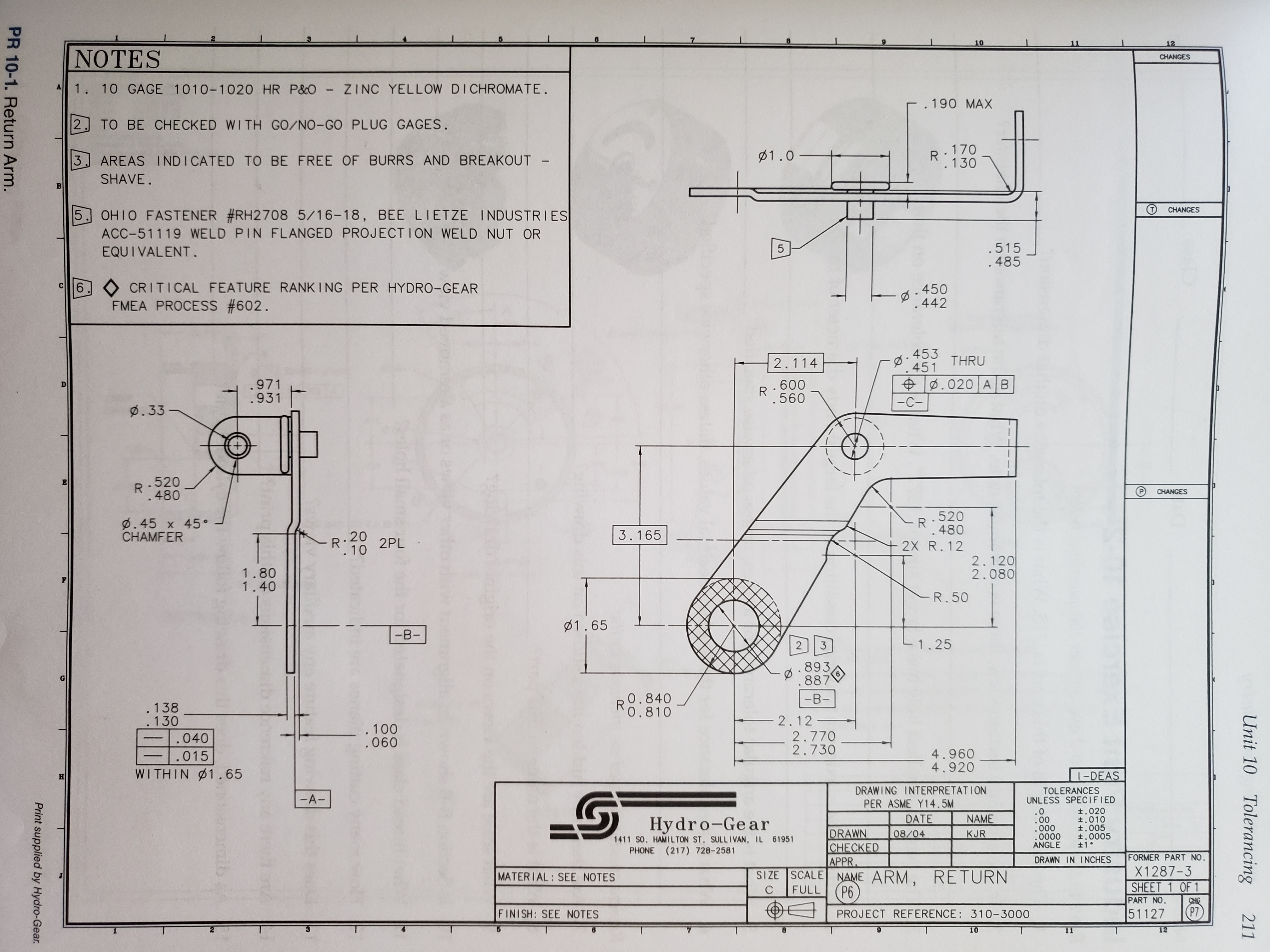
Transcribed Image Text:10
12
NOTES
CHANGES
1. 10 GAGE 1010-1020 HR P&O ZINC YELLOW DI CHROMATE.
.190 MAX
TO BE CHECKED WITH GO/NO-GO PLUG GAGES.
2
170
R
.130
1.0
3
AREAS INDICATED TO BE FREE OF BURRS AND BREAKOUT -
SHAVE.
CHANGES
OHIO FASTENER #RH2708 5/16-18, BEE LIETZE INDUSTRIES
ACC-51119 WELD PIN FLANGED PROJECT I ON WELD NUT OR
EQUI VALENT.
.515
.485
5
CRITICAL FEATURE RANK I NG PER HYDRO-GEAR
FMEA PROCESS #602
6
450
.442
453
451
THRU
2.114
.020 A B
.971
.931
.600
R
0.560
-C-
Ø. 33
+
R 520
.480
CHANGES
.520
R
.480
ø.45 x 45
CHAMFER
R 20
. 10
3.165
2PL
2X R. 12
2.120
2.080
1.80
1.40
-R. 50
1.65
-В-
1.25
2
3
893
.887
0.840
R
0.810
-B-
.138
.130
2.12-
.100
.060
2.770
2.730
.040
4.960
4.920
-.015
WITHIN 1. 65
1-DEAS
DRAWING INTERPRETATION
TOLERANCES
UNLESS SPECIFIED
0.0
.00
.000
.0000
ANGLE
-A-
PER ASME Y14.5M
t.020
t.010
t.005
t.0005
±1
Hydro-Gear
1411 SO. HAMILTON ST. SULLIVAN, IL 61951
PHONE (217) 728-2581
DATE
08/04
NAME
DRAWN
CHECKED
APPR
NAME ARM, RETURN
P6
KJR
FORMER PART NO.
DRAWN IN INCHES
X1287-3
SHEET 1 OF 1
PART NO.
51127
SIZE SCALE
MATERIAL: SEE NOTES
FULL
С
CHIG
P7
FINISH: SEE NOTES
PROJECT REFERENCE : 310-3000
12
10
11
Unit 10 Tolerancing
211
Print supplied by Hydro-Gear.
PR 10-1. Return Arm.
Expert Solution
This question has been solved!
Explore an expertly crafted, step-by-step solution for a thorough understanding of key concepts.

This is a popular solution!
Step 1
VIEW
Trending now
This is a popular solution!

Step by step
Solved in 1 steps with 1 images

Knowledge Booster


Learn more about
Need a deep-dive on the concept behind this application? Look no further. Learn more about this topic, mechanical-engineering and related others by exploring similar questions and additional content below.Recommended textbooks for you
Elements Of Electromagnetics
Mechanical Engineering
ISBN:
9780190698614
Author:
Sadiku, Matthew N. O.
Publisher:
Oxford University Press

Mechanics of Materials (10th Edition)
Mechanical Engineering
ISBN:
9780134319650
Author:
Russell C. Hibbeler
Publisher:
PEARSON

Thermodynamics: An Engineering Approach
Mechanical Engineering
ISBN:
9781259822674
Author:
Yunus A. Cengel Dr., Michael A. Boles
Publisher:
McGraw-Hill Education
Elements Of Electromagnetics
Mechanical Engineering
ISBN:
9780190698614
Author:
Sadiku, Matthew N. O.
Publisher:
Oxford University Press
Mechanics of Materials (10th Edition)
Mechanical Engineering
ISBN:
9780134319650
Author:
Russell C. Hibbeler
Publisher:
PEARSON
Thermodynamics: An Engineering Approach
Mechanical Engineering
ISBN:
9781259822674
Author:
Yunus A. Cengel Dr., Michael A. Boles
Publisher:
McGraw-Hill Education

Control Systems Engineering
Mechanical Engineering
ISBN:
9781118170519
Author:
Norman S. Nise
Publisher:
WILEY

Mechanics of Materials (MindTap Course List)
Mechanical Engineering
ISBN:
9781337093347
Author:
Barry J. Goodno, James M. Gere
Publisher:
Cengage Learning

Engineering Mechanics: Statics
Mechanical Engineering
ISBN:
9781118807330
Author:
James L. Meriam, L. G. Kraige, J. N. Bolton
Publisher:
WILEY