Design Problem: A pattern recognizer with a 1-bit output n accepts a 1-bit input m. Output n becomes 1 only if th 0-1-0 pattern is seen at m (m is sampled every clock cycle). The circuit treats the incoming bit stream as overlapping sequences, i.e. the last bit of a previous sequence becomes the first bit of the next sequence. In effect, the circuit looks at the most recent three bits to check against the pattern, like below: m n 0 0 1 0 1 1 0 1 0 1 0 1 1 0 0 0 1 0 0 0 0 1 0 1 0 0 Design a Moore-type circuit (using D-flipflop) for the pattern recognizer described above.
Design Problem: A pattern recognizer with a 1-bit output n accepts a 1-bit input m. Output n becomes 1 only if th 0-1-0 pattern is seen at m (m is sampled every clock cycle). The circuit treats the incoming bit stream as overlapping sequences, i.e. the last bit of a previous sequence becomes the first bit of the next sequence. In effect, the circuit looks at the most recent three bits to check against the pattern, like below: m n 0 0 1 0 1 1 0 1 0 1 0 1 1 0 0 0 1 0 0 0 0 1 0 1 0 0 Design a Moore-type circuit (using D-flipflop) for the pattern recognizer described above.

Introductory Circuit Analysis (13th Edition)
13th Edition
ISBN:9780133923605
Author:Robert L. Boylestad
Publisher:Robert L. Boylestad
Chapter1: Introduction
Section: Chapter Questions
Problem 1P: Visit your local library (at school or home) and describe the extent to which it provides literature...

Related questions
Question
Construct/Draw the Moore-type circuit
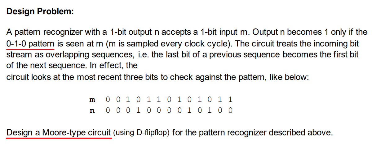
Transcribed Image Text:Design Problem:
A pattern recognizer with a 1-bit output n accepts a 1-bit input m. Output n becomes 1 only if the
0-1-0 pattern is seen at m (m is sampled every clock cycle). The circuit treats the incoming bit
stream as overlapping sequences, i.e. the last bit of a previous sequence becomes the first bit
of the next sequence. In effect, the
circuit looks at the most recent three bits to check against the pattern, like below:
m
n
0 0 1 0 1 1 0 1 0 1 0 1 1
0 0 0 1 0 0 0 0 1 0 1 0 0
Design a Moore-type circuit (using D-flipflop) for the pattern recognizer described above.
Expert Solution
This question has been solved!
Explore an expertly crafted, step-by-step solution for a thorough understanding of key concepts.

This is a popular solution!

Trending now
This is a popular solution!

Step by step
Solved in 3 steps with 3 images

Knowledge Booster


Learn more about
Need a deep-dive on the concept behind this application? Look no further. Learn more about this topic, electrical-engineering and related others by exploring similar questions and additional content below.Recommended textbooks for you
Introductory Circuit Analysis (13th Edition)
Electrical Engineering
ISBN:
9780133923605
Author:
Robert L. Boylestad
Publisher:
PEARSON

Delmar's Standard Textbook Of Electricity
Electrical Engineering
ISBN:
9781337900348
Author:
Stephen L. Herman
Publisher:
Cengage Learning

Programmable Logic Controllers
Electrical Engineering
ISBN:
9780073373843
Author:
Frank D. Petruzella
Publisher:
McGraw-Hill Education
Introductory Circuit Analysis (13th Edition)
Electrical Engineering
ISBN:
9780133923605
Author:
Robert L. Boylestad
Publisher:
PEARSON
Delmar's Standard Textbook Of Electricity
Electrical Engineering
ISBN:
9781337900348
Author:
Stephen L. Herman
Publisher:
Cengage Learning
Programmable Logic Controllers
Electrical Engineering
ISBN:
9780073373843
Author:
Frank D. Petruzella
Publisher:
McGraw-Hill Education

Fundamentals of Electric Circuits
Electrical Engineering
ISBN:
9780078028229
Author:
Charles K Alexander, Matthew Sadiku
Publisher:
McGraw-Hill Education

Electric Circuits. (11th Edition)
Electrical Engineering
ISBN:
9780134746968
Author:
James W. Nilsson, Susan Riedel
Publisher:
PEARSON

Engineering Electromagnetics
Electrical Engineering
ISBN:
9780078028151
Author:
Hayt, William H. (william Hart), Jr, BUCK, John A.
Publisher:
Mcgraw-hill Education,