Draw the shear force and bending moment diagrams for the following beam.


Q: Draw the shear and bending moment diagrams by developing the equations for shear and bending moment…
A: Given data:
Q: 50kN 10KN/m 2.5 2.5 3 LO
A:
Q: Draw the shear and moment diagrams for the beam shown in figure below. Write down the name of this…
A: This type of problems are solved by using the separation technique, the above figure is divided into…
Q: Draw the complete shear and moment diagrams for the beam shown below
A:
Q: ВEAM 3: DRAW THE SHEAR AND MOMENT DIAGRAMS OF THE FOLLOWING BEAMS. WRITE THE SHEAR AND MOMENT…
A:
Q: Use the graphical method to construct the shear-force and bending-moment diagrams for the beam…
A: Solution
Q: Q3/ Use the graphical method to draw the shear force and bending moment diagrams for the beam shown.…
A: Use the graphical method to draw the shear force and bending moment diagrams for the beam shown.
Q: Draw the shear force and bending moment diagrams for the beam.
A: Hi! Thank you for the question As per the honor code, We’ll answer one question since the exact one…
Q: Q3/ Use the graphical method to draw the shear force and bending moment diagrams for the beam shown.…
A: to draw sfd and bmd
Q: For each beam shown below, draw the shear force diagram and bending moment diagram
A: A loaded beam is given and it has been asked to draw shear force and bending moment diagram. Please…
Q: Draw the moment diagram by parts of the beams shown using points A, B, and C as the reference for…
A:
Q: Draw the shear-force and bending-moment diagrams for the beam shown. PROVIDE A DETAILED AND COMPLETE…
A:
Q: draw shear force and bending moment diagrams for the beam shown
A: Draw the figure.
Q: I. Draw the Shear and Moment Diagram of the given beam.
A: For the given beam, the shear and moment diagrams are to be drawn.
Q: Draw shear and bending moment diagrams for the beam.
A:
Q: Draw the shear force, bending moment and thrust diagrams for the beam.
A:
Q: REMEMBER
A:
Q: Draw the shear force and bending moment diagrams of the following beams.
A: Given:- A beam is given with hinge and roller support The magnitude of the point load = 1500 lb The…
Q: Q3/ Use the graphical method to draw the shear force and bending moment diagrams for the beam shown.…
A: To draw SFD and BMD
Q: 10 Ibs 5 ft 10 ft
A: A loaded beam is given and it has been asked to draw shear force and bending moment diagram. Please…
Q: Draw shear force and bending moment diagram for the above beam
A: the given beam is cantilever beam with moment at the end and point load at the center. this beam is…
Q: Determine the equations for shear and bending moment for the beam shown. Use the resulting equations…
A: Shear Force Shear force is the force that comes into play when the beam under load condition and the…
Q: Sketch the shear and moment diagrams for a compound beam shown.
A:
Q: 30 kN A 1m B 3 m 50 kN C 2 m D
A: The length of beam, L=6mThe loads are 30KN, 50KN
Q: 1. Given the Shear Diagram of the statically determinate beam, draw the load diagram and moment…
A: In shear force diagram Straight line indicate there is no load between that two point. Inclined line…
Q: 10 kip 8 kip 2 kip/t 40 kip-ft 6 ft 4 ft-
A: Since this is a determinant beam we can solve for SFD and BMD with the equilibrium equations as the…
Q: equations
A:
Q: Draw the shear and bending moment diagrams for the beam that shown. Solve for the maximum shear and…
A: Need to draw shear force and bending moment diagram
Q: Draw the shear force and bending moment diagram for the following beam
A: Data given: Asked: Draw the shear force and bending moment diagram for the following beam
Q: Draw the shear and bending moment diagrams for the shown beam loaded
A:
Q: Draw the shear, moment, axial and elastic curve diagram of the beam
A:
Q: Draw shear force and bending moment diagrams for the beam shown below
A: Solution
Q: Develop the shear force and bending moment diagrams for the different segments of the beam. Use that…
A: Given:- To find:- Shear force and bending moment diagram
Q: 300 K/ft 9000 K-ft 100 K/ft E A |B hinge 6 ft 6 ft 12 ft 6 ft
A:
Q: Draw the shear and moment diagrams of the beam shown below. Assume joint at B is roller, C is pin…
A:
Q: Write the shear and moment equations and Draw the shear and moment diagrams for the beam
A:
Q: Write the equation of shear and moment as a function of x for each segment of the following beam,…
A: Shear Force- It is the summation of all the forces acting laterally to the beam. Bending…
Q: Shear and Moment Diagrams
A:
Q: Draw the shear force diagrams and bending moment for the illustrated beam
A: To determine reactions we will be using equilibrium equations. When reactions are calculated then…
Q: Draw the load and the bending moment diagrams that correspond to the given shear force diagram.…
A:
Q: Draw the shear-force and bending-moment diagrams for the beam shown. Determine the maximum shear and…
A: Given:- To find:- Shear force and bending moment diagram Maximum shear and maximum bending moment
Q: Draw shear force and bending moment diagrams for the beam hown below and then find max. shear force…
A:
Q: Determine the values of shear and moment. Draw the elastic curve, shear diagram, and moment diagram…
A:
Q: 18 KN (a) (b) 30KN 10 KN 20AN SKNm 王 to
A: Shear forces Shear forces are algebraic sum of all the forces acting on beam . We have taken upward…
Q: Write the shear and moment equations for the beam loaded as shown and sketch the shear and moment…
A:
Q: From the given figures below, draw the shear and moment diagram of the beam.
A: Force in the vertical directionRA + RE = 10×6 + 30 + 16×12 + 20⇒RA + RE = 302 ....1Sum of…
Q: Draw the shear force and bending moment diagrams for the beam shown in the figure below. 80 kip 3…
A:
Q: Write the shear and moment equations and Draw the shear and moment diagrams for the beams shown
A:
Q: Draw Shear and Moment Diagrams for each of the beams below and find max bending stress. Every beam…
A:
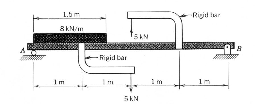
Draw the shear force and bending moment diagrams for the following beam.


Trending now
This is a popular solution!

Step by step
Solved in 5 steps with 2 images


- Compute the nominal shear strength of an M107.5 of A572 Grad 65 steel.A W12x79 of A573 Grade 60 (Fy = 415 MPa) steel is used as a compression member. It is 8 m long, pinned at the top fixed at bottom with additional lateral support at mid height in the weak direction. The properties are as follows: Ag = 14,500 sq.mm, Ix= 258.6 x10^6 mm ^4 Iy=84.375 x 10^6 mm^4. 57. Calculate the flexural buckling stress Fcr in MPaA flooring system consist of I-beam sections spaced at 3 m(center to center) and with simple spans of 6 m. The beams support a 200 mm thick slab. The flooring system is designed for a live load of 2400 N/m² as well as ceiling load of 750 N/m². The properties of the I-beam sections are : d = 352 mm, weight of beam = 440 N/m, moment of inertia , Ix = 0.0012 m⁴. Consider Fy = 248 MPa, E = 200000 MPa and wt. of concrete of 24 kN/m³. 1. Which of the following most nearly gives the uniform pressure acting on the slab? a. 6.2 kPa b. 7.95 kPa c. 5.2 kPa d. 6.10 kPa 2. Which of the following most nearly gives the total uniform load on the beam in kN/m? a. 19.71 kN/m b. 17.82 kN/m c. 24.29 kN/m d. 28.14 kN/m 3. Which of the following most nearly gives the initial stress on the beam due to deadload only assuming no shoring during construction? a. 12.1 MPa b. 8.91 MPa c. 10.4 MPa…
- A W12x79 of A573 Grade 60 (Fy = 415 MPa) steel is used as a compression member. It is 7 m long, pinned at the top fixed at bottom, and has additional support in the weak direction 3 m from the top. Properties of the section are as follows: A = 14,500 mm^2 Ix = 258.6 x 10^6 mm^4 Iy = 84.375 x 10^6 mm^4 1. Calculate the critical slenderness ratio of the member. a. 26.208 b. 45.882 c. 36.706 d. 27.529 2. calculate the nominal axial load capacity of the column a. 3104 kN b. 4851 kN c. 4213 kN d. 5344 kN 3. calculalte the service axial dead load if the service axial live load is twice as that of the dead load. Use LRFD. a. 1354 kN b. 992 kN c. 1093 kN d. 634 kNA WF section of A572 Grade 60 steel is used as a compression member. It is 7.7 meters long, fixed at both ends, and has additional support in the weak direction at a point 3.4 meters from the top. The member resists a service dead load of 800 KN and a service liveload of 1200 KN. WF properties: A=23,973mm2, rx=135mm, ry=68mm. Calculate the largest slenderness ratio of the column. Express your answer in 2 decimal places.12 A W12x79 of A573 Grade 60 (Fy = 415 MPa) steel is used as a compression member. It is 6.8 m long, fixed at the top and bottom, and has additional support in the weak direction at mid-height. Properties of the section are as follows: A = 14,500 mm^2 Ix = 258.6 x 10^6 mm^4 Iy = 84.375 x 10^6 mm^4 Calculate the critical slenderness ratio with respect to weak axis buckling using theoretical value of k.
- A W 360 x 744 is used as a beam to support a concrete floor system. The floor is to carry atotal load of 250 kPa. The beam is simply supported over a span of 6 m. Assume the beamis laterally supported over its length. Use A36 steel with Fy = 250 MPa. Allowabledeflection is L/360.a. Determine the center to center spacing of the beams without exceeding the allowableshear stress.b. Determine the center to center spacing of the beams without exceeding the allowablebending stress.c. Determine the center to center spacing of the beams without exceeding the allowabledeflection.Axial loads are applied to the compound rod that is composed of an aluminum segment rigidly connected between steel and bronze segments. What is the stress in each material given that P-10 kN? Draw the FREE BODY DIAGRAM.A W12x79 of A573 Grade 60 (Fy = 415 MPa) steel is used as a compression member. It is 7.8 m long, fixed at the top and bottom, and has additional support in the weak direction at mid-height. Properties of the section are as follows: A = 14,500 mm^2 Ix = 258.6 x 10^6 mm^4 Iy = 84.375 x 10^6 mm^4 Calculate the effective slenderness ratio with respect to strong axis buckling using theoretical value of k.
- Situation 17. A w12x79 of A573 Grade 60 (Fy-415MPa) steel is used as a compression member. It is 8m long pinned at the top fixed at bottom with additional lateral support at mid height in the weak direction. The properties are as follows Ag=14,500 sq.mm = 258.6x10^6 mm^4 Iy=84.375x10^6 mm^4 Calculate the critical slenderness ratio with buckling about strong axis. calculate the critical slenderness ration with buckling about weak axis. calculate the flexural buckling stress Fcr in MPAA W12x79 of A573 Grade 60 (Fy = 415 MPa) steel is used as a compression member. It is 8 m long, pinned at the top fixed at bottom with additional lateral support at mid height in the weak direction. The properties are as follows: Ag = 14,500 sq.mm, Ix= 258.6 x10^6 mm ^4 Iy=84.375 x 10^6 mm^4. 55. calculate the critical slenderness ratio with buckling about strong axis.The simply supported beam consists of a W21 × 44 structural steel wide-flange shape [E = 29,000 ksi; I = 843 in.4]. Assume d = 5 ft, w = 3 kips/ft, P = 48 kips. For the loading shown, determine (a) the beam deflection at point A. (b) the beam deflection at point C.