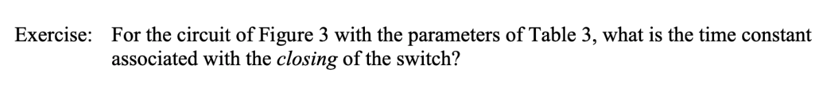
Exercise: For the circuit of Figure 3 with the parameters of Table 3, what is the time constant associated with the closing of the switch? R2 R1 4 V Figure 3: RL circuit Table 3: Component values for Figure 3 L R1 3 kΩ R2 3 kΩ 300 mH


Q: 3. If we use a digital voltmeter to measure the voltages across the middle resistor in the circuit…
A: Here question 3 and 4 are asked for question 3 complete data is given which is required from…
Q: 3.84.1 In the circuit shown in the image below, if V1 = 17.4 mV and R1 determine voltage vo in V. =…
A: Kirchhoff's Voltage Law The algebraic sum of the voltage differences around any closed loop path is…
Q: As a design engineer, you are asked to design a lighting system consisting of a 70-W power supply…
A:
Q: c. Use KCL to determine the current i, izis for the circuit given in figure 3 12 mA 8 mA 9 mA Figure…
A: Find the current i1 i2 i3 in the circuit using the KCL.
Q: The switch is now closed[the switch has no resistance] (h) R2 t + & = 0 q = Ce • Vc = ce¯# ; VRa =…
A: Let voltage across capacitor be VC and that across resistor be VR Apply KVL in loop 2,…
Q: 1)A moving coil instrument gives a full scale deflection of 30mA, when the potential difference of…
A: Dear student as per our guidelines we are supposed to solve only one question.kindly repost other…
Q: Q2: The switch (SW) in the circuit is opened for a long time shown Figure 2. A. Calculate the…
A:
Q: QUESTION 1 What is the Norton equivalent current In and resistance Rn the circuit below. Express any…
A:
Q: Q4. In the meters shown below, if you have to choose them based on their abilities which is…
A: Time-invariance: For the time-invariance system, the time delay provided in the input must be…
Q: Question 2: In the circuit shown in Figure 1.4, the switch is moved from position X to position Y at…
A:
Q: Two tram cars (A & B) 2 km and 6 km away from a sub-station return 40 A and20 A respectively to the…
A:
Q: II Revie The circuit shown in (Figure 1) contains a voltage- controlled current source. Suppose i =…
A: Given, The circuit is, Current, i=1.5 A.
Q: 1. A moving coil meter with meter resistance Rm of 1000 and a full scale meter current Im equals to…
A: In this question, design the voltage series multiplayer circuit. If PMMC meter current rating =…
Q: Analytically (show all necessary work) determine the Thévenin equivalent circuit seen by the 2.2 kN…
A:
Q: For the circuit shown below, for R1=570, R2=660, k1=7, k2=6, k3=10, V1=5 v and V2=9 v use KCL, KVL…
A: Note: We are authorized to answer three subparts at a time, since you have not mentioned which part…
Q: A battery with Ɛ = 9.00 V and no internal resistance supplies current to the circuit shown in the…
A:
Q: An aluminium wire 7.5 m long is connected in a parallel with a copper wire 6 m long. When a current…
A: 4
Q: An aluminum wire 7.5 m long is connected in parallel with a copper wire 6 m long. When a current of…
A: It is Given that: Length of alminium wire LA=7.5mLength of copper wire LC=6mTotal current=5ACurrent…
Q: Required information No currents flow in the circuit diagrammed before the switch is closed.…
A:
Q: 220 2 470 2 R3 R2 Š130 2 12 volts
A:
Q: Find 1 in the circuit shown. 2 ΚΩ 2 k2 12 mA 10 k2 2 kN 2 k2 Select one: a. 12 mA Ob.3 mA C. 4 mA d.…
A: In this question we will find unknown current I 1..
Q: 4. Find the hot resistance of a lightbulb rated 60 W, 120 V. 5. When the voltage across a resistor…
A: Note : as per guideline we have to solve one question at a time if different ques posted please…
Q: Solve the following. Show complete solution, resistor combination and circuit transformation. Box…
A:
Q: The switch (SW) in the circuit is opened for a long time shown Figure 2. A. Calculate the expression…
A:
Q: (b) A small storage battery has an open circuit voltage of 6.5 V and an internal resistance of 0.02…
A:
Q: In the circuit below, the switch was turned to the 2 position at t=0 after being in the 1 position…
A: According to question: The initial voltage across the capacitor is calculated as…
Q: The circuit shown below consists of resistors, capacitors, a battery, and a single pole double throw…
A: R= 10 II 7.5+ 4.5 = 10 II 12 = 10×1210+12 = 5.45 M C = 70 II 45 =70×4570+45=27.4μF
Q: 13.) Fill in the blank: The ammeters and voltmeters record the r.m.s. values of "and voltage…
A: We need to fill the blank space for given statement
Q: Part B Given the following circuit F1 SW1 SW2 Sw3 SW4 SW5 SW6 BAT1 R1 R2 24 0 R3 R4 R5 R6 12 V 12 0…
A: Given
Q: 2. Figure 1 shows a voltmeter connection with 15 kO/ sensitivity, connected across Rb. Calculate the…
A: The solution is given below
Q: Q17. For the circuit shown in Figure B2, when the switch opened at t=0 sec, 120V 3.3KN 10 mH Figure…
A: For the circuit shown in figure B2 ,when the switch opened at t=0sec, calculate the following: i)…
Q: 2.52 E 3 S2 10.3 V H. F D
A:
Q: You are presented with a sealed box containing a circuit, this box has two terminals a and b, where…
A:
Q: Q2: The switch (Sw) in the circuit is opened for a long time shown Figure 2. A. Calculate the…
A: The circuit is as shown below :
Q: Exercise: For the circuit of Figure 3 with the parameters of Table 3, what is the time constant…
A: The given circuit is series RL circuit, the time constant of this circuit is given by:-
Q: but do not solve, the equations of motion for the mechanic network of Figure 5 KI K2
A: For spring:F(t)=k x(t)for mass:F(t)=ma=mdx2(t)dt2for viscous damper:F(t)=fvdx(t)dtwhere, k is spring…
Q: Circuit 2 Calculated Total Resistance: Measured Total Resistance: Theoretical Measured Percent Error…
A: The required equivalent resistance, Voltage across the resistor, and current through the resistors…
Q: Q2: The switch (SW) in the circuit is opened for a long time shown Figure 2. A. Calculate the…
A: Time t<0 Switch open For long time, inductor act as short circuit. t=0 switch close Find the…
Q: You and a group of friends are on a day trip to a nearby national park. After a fun-filled day of…
A: Live battery has voltage εL=12 volt and it has a resistance of 0.01 ohm Dead battery has voltage…
Q: Question 3 R2 R V1 R1 For the above circuit V=9 Volts R1=6 Ohms, R2=4 Ohms R3=6 Ohms, R4=4 Ohms…
A: Given: v1 = 9v ,R1=R3=6 ohms, R2=R3=4 ohm Calculate: thevenin voltage across a- b terminal.
Q: Multi-range DC Voltmeter Homework Design (0-250) V, (0- 400 V) and (0-700)V multi range DC voltm…
A: in this question , we have to convert meter into multi range voltmeter...And find out the value of…
Q: B3 A voltmeter having a sensitivity of 800 22/V reads 50V on its 90V range, when connected across an…
A:
Q: I Review I Constants A voltmeter with a resistance of 85 kn is used to measure the voltage Vab in…
A:
Q: For the circuit shown, change the value of resistor R as follows [1k, 3k, 5k, 7k, 10k] then 1.…
A: (1) Calculate the ammeter and the voltmeter readings when R = 1kΩ. A=48 V500 Ω+1000 Ω=32 mAV=1000…
Q: An aircraft has two flaps that fixed with wing used in landing and takeoff, when the aircraft…
A: It is given that there are two flaps for the aircraft. We denote them as Flap1 and Flap2. Flap1…
Q: 3. Define voltage on resistance R, at the first time after switching UR, (0.), if e(t)=10 sin(or +…
A: In this question, Voltage across the resistance R2 at first time after switching UR2 (0+ ) We are…
Q: The power usage of a DC strip heater can be determined in either of two ways: (1) Heater resist-…
A:

Step by step
Solved in 3 steps with 3 images

- Please explain how does the circuit work base on the given diagram circuit.The response to the question I have asked here... "2. Sometimes light fixtures are controlled by more than one switch. Circuits need to be designed so that flipping one of the switches turns the light on when it is off, and turns the light off when it is on. Design logical circuit that accomplishes this when there are two switches. Explain, how and why will your circuit work. Please draw the circuit and show logical operations. (Can only use or, not, and)" Does not seem right as what you provided gives a truth table of if both switches are off the light fixture would be on which should not be the case and does not make sense in context of the question asked. Also the circuit drawing doesn't seem right... Can you re-explain cause what you provided as the answer is not making much sense... A' solely being what determines if fixture is on or off does not seem right at all...2. Sometimes light fixtures are controlled by more than one switch. Circuits need to be designed so that flipping one of the switches turns the light on when it is off, and turns the light off when it is on. Design logical circuit that accomplishes this when there are two switches. Explain, how and why will your circuit work. Please draw the circuit and show logical operations. (Can only use or, not, and)
- Explain in your own words how the Battery testing (performance test) is applied to the patient turning apparatus shown in the figure, and guess how the expected result will be. In addition, there are heating pads working with the logic of electric blankets in this apparatus but consider that it works with a battery, not a plug. Please answer by taking these into account when answering.Discuss how the circuit works. (MAXIMUM OF 10 SENTENCES.)1)Answer the following questions in not more than 5 sentences. a Describe the elements of a sequential circuit and the functions it must perform. b. Differentiate gated S-R latch from a normal S-R latch. c.Describe the following state diagram and discuss fully the states illustrated below
- Can someone please verify both circuits components are within their min/max limits? I have a hard time understanding the data sheets Will upvote! Same components used for both. Table with operating voltage and current attachedAre the following statements correct or wrong? Justify your answer. (a) GTO requires very high current applied to its gate to be turn off. (b) IGBT is a current driven device. (c) IGBT is more efficient than BJT in high power applications. (d) Thyristors are used only for low voltage, low current applicationssolve the question and describe the all steps.