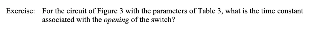
Exercise: For the circuit of Figure 3 with the parameters of Table 3, what is the time constant associated with the opening of the switch? R2 R1 4 V Figure 3: RL circuit Table 3: Component values for Figure 3 L R1 3 kΩ R2 3 kΩ 300 mH


Q: 3. If we use a digital voltmeter to measure the voltages across the middle resistor in the circuit…
A: Here question 3 and 4 are asked for question 3 complete data is given which is required from…
Q: 1. Construct the circuit shown above. 2. Measure the values of , L, hand lgusing Digital Multimeter…
A:
Q: As a design engineer, you are asked to design a lighting system consisting of a 70-W power supply…
A:
Q: c. Use KCL to determine the current i, izis for the circuit given in figure 3 12 mA 8 mA 9 mA Figure…
A: Find the current i1 i2 i3 in the circuit using the KCL.
Q: iii) The switch Si in Figure 5 is closed for long time and then opened at t= 0, calculate the…
A: Given circuit, Resistance of air gap is 1.2 MΩ
Q: The switch is now closed[the switch has no resistance] (h) R2 t + & = 0 q = Ce • Vc = ce¯# ; VRa =…
A: Let voltage across capacitor be VC and that across resistor be VR Apply KVL in loop 2,…
Q: (a) Circuit with open switch (b) Circuit with closed switch Figure 1. Circuit diagram with switch.…
A:
Q: QUESTION 1 What is the Norton equivalent current In and resistance Rn the circuit below. Express any…
A:
Q: а. Find the equivalent resistance REg for the resistor combination circuit provided in figure 4. 202…
A:
Q: I= R V=3-2=1 + Arode Led VL=2v Cathode
A:
Q: What will happen to Bulb B when Switch B is closed? Explain and justify your answer briefly in…
A: The circuit is shown below has a battery with the Switch after it, Switch A, Switch B, and Switch C…
Q: 3. Design an Ayrton Shunt that can measure up to 1A, 2A, 3A and 4A if the meter movement has a…
A:
Q: Figure 1 shows the circuit diagram of an automotive lighting system, and all lamps has 500 Q…
A: Thi circuit under consideration is as shown below :
Q: Question 2: In the circuit shown in Figure 1.4, the switch is moved from position X to position Y at…
A:
Q: II Revie The circuit shown in (Figure 1) contains a voltage- controlled current source. Suppose i =…
A: Given, The circuit is, Current, i=1.5 A.
Q: R, R, OUT IN E OuT А. B.
A: Here is the detail solution
Q: 3. Figure 1 shows the circuit diagram of an automotive lighting system, and all lamps has 500 Q…
A:
Q: Exercise: For the circuit of Figure 1 with the parameters of Table 1, what is the time constant…
A: The given circuit is series RC circuit, the time constant of this circuit is given by:-
Q: Part 2: Lightbulbs (A) B 1) Consider the circuit above, where A, B, and C are equal lightbulbs. What…
A: We are authorized to answer one question at a time, since you have not mentioned which question you…
Q: 10. A voltmeter with resistance 'Rv' is connected in parallel with resistance R=100 ohms. The…
A: 10. It is given that: R=100 ΩV=100 V
Q: Exercise: For the circuit of Figure 3 with the parameters of Table 3, what is the time constant…
A: Write the expression for time constant of RL-circuit,
Q: An aluminium wire 7.5 m long is connected in a parallel with a copper wire 6 m long. When a current…
A: 4
Q: A 0-10Vdc voltmeter has a sensitivity of 50052/V. Would this meter accurately indicate 4. a ten volt…
A: We are supposed to be answer of first question as per guildlines for second question you have to…
Q: 2. Draw a circuit for each of these acts that adheres to the particular given requirements. (Label…
A: Switches- Switches are used to connect a one circuit to another or to allow the passage of current…
Q: 4. Find the hot resistance of a lightbulb rated 60 W, 120 V. 5. When the voltage across a resistor…
A: Note : as per guideline we have to solve one question at a time if different ques posted please…
Q: Solve the following. Show complete solution, resistor combination and circuit transformation. Box…
A:
Q: Solve the following. Show complete solution, resistor combination and circuit transformation. Box…
A:
Q: The switch (SW) in the circuit is opened for a long time shown Figure 2. A. Calculate the expression…
A:
Q: (b) A small storage battery has an open circuit voltage of 6.5 V and an internal resistance of 0.02…
A:
Q: Figure Q2(c) is a circuit which contains several meshes. Determine the voltage across 6 kN resistor…
A: Redraw the circuit and represent the node voltages.
Q: A 9-volt battery with a 500 mAh capacity is connected to a circuit which draws 100 mA. How long will…
A: In this question given battery capacity is given and current drawn by circuit is also given...We…
Q: ww R1 R3 Vg R2 R4 ww ++
A: Solve for above questions
Q: * CENGAGE MINDTAP Q Search this course Unit 7 Practical Applications PRACTICAL APPLICATIONS 1. You…
A: As per Bartleby expert policy only first individual question is to be answered. Kindly repost second…
Q: 13.) Fill in the blank: The ammeters and voltmeters record the r.m.s. values of "and voltage…
A: We need to fill the blank space for given statement
Q: 3. Determine the voltage (V;) at the first resistor (R1 = 2.41 2) for the circuit diagram below. %3D…
A: In this question, We need to determine the voltage V1 at the first resistance R1.?
Q: Part B Given the following circuit F1 SW1 SW2 Sw3 SW4 SW5 SW6 BAT1 R1 R2 24 0 R3 R4 R5 R6 12 V 12 0…
A: Given
Q: Q3: Suppose that the components of the circuit shown in figure below, have the following values: R1=…
A: Given data- R1=16 ΩR2=18 ΩR3=30 ΩR4=9 ΩR5=4 ΩRm=250 Ω
Q: 3. Figure 1 shows the circuit diagram of an automotive lighting system, and all lamps has 500 Q…
A:
Q: Example 3.4 (b) Calculate the value of the shunt resistors for the circuit shown below. Rm = 1k2 Im…
A:
Q: Table 4.6. R2 100 ohms 12V R1 R4 1k ohm 470 ohms 330 ohms Figure 4.7 Table 4.2 Analyze the…
A:
Q: . Design a circuit for each of these acts that adheres to the particular given requirements.…
A: Switch- A switch is a device which is used to allow or disallow the electric energy to pass through…
Q: but do not solve, the equations of motion for the mechanic network of Figure 5 KI K2
A: For spring:F(t)=k x(t)for mass:F(t)=ma=mdx2(t)dt2for viscous damper:F(t)=fvdx(t)dtwhere, k is spring…
Q: 1. A small wire or device inside a piece of electrical equipment that breaks and stops current if…
A: We are authorized to answer three subparts at a time, since you have not mentioned which part you…
Q: You and a group of friends are on a day trip to a nearby national park. After a fun-filled day of…
A: Live battery has voltage εL=12 volt and it has a resistance of 0.01 ohm Dead battery has voltage…
Q: I Review I Constants A voltmeter with a resistance of 85 kn is used to measure the voltage Vab in…
A:
Q: R2 R R4 Rs Rs E, V, V2 (b) (a) Figure 3
A: Resistors, inductors and capacitors form an integral part of any electrical circuit. A source,…
Q: An aircraft has two flaps that fixed with wing used in landing and takeoff, when the aircraft…
A: It is given that there are two flaps for the aircraft. We denote them as Flap1 and Flap2. Flap1…
Q: Current Mirror In Figure 1, If the two NMOS have the same parameters and the resistors are the same,…
A: Figure 1 is given as' Since transistors M1 and M2 are matched transistors and so that the given…
Q: A room 100 ft x 300 ft requires 80 foot-candle. It is to be illuminated by duplex fluorescent lamp.…
A:
Q: his question from Measurements and Instrumentation course. Please,solve all parts;its Easy for…
A: Given data Vmax=5VVmin=0Vn=12 a-(i) Maximum percentage quantisation error is…


Trending now
This is a popular solution!

Step by step
Solved in 3 steps with 3 images

- Explain the operation of the following circuit:Use Visio to draw a circuit that implements an Exclusive OR circuit, using only basic gates. Insert your drawing here.The response to the question I have asked here... "2. Sometimes light fixtures are controlled by more than one switch. Circuits need to be designed so that flipping one of the switches turns the light on when it is off, and turns the light off when it is on. Design logical circuit that accomplishes this when there are two switches. Explain, how and why will your circuit work. Please draw the circuit and show logical operations. (Can only use or, not, and)" Does not seem right as what you provided gives a truth table of if both switches are off the light fixture would be on which should not be the case and does not make sense in context of the question asked. Also the circuit drawing doesn't seem right... Can you re-explain cause what you provided as the answer is not making much sense... A' solely being what determines if fixture is on or off does not seem right at all...
- What rule it's ? Explain your solution.Please explain how does the circuit work base on the given diagram circuit.2. Sometimes light fixtures are controlled by more than one switch. Circuits need to be designed so that flipping one of the switches turns the light on when it is off, and turns the light off when it is on. Design logical circuit that accomplishes this when there are two switches. Explain, how and why will your circuit work. Please draw the circuit and show logical operations. (Can only use or, not, and)
- 1)Answer the following questions in not more than 5 sentences. a Describe the elements of a sequential circuit and the functions it must perform. b. Differentiate gated S-R latch from a normal S-R latch. c.Describe the following state diagram and discuss fully the states illustrated belowExplain in your own words how the Battery testing (performance test) is applied to the patient turning apparatus shown in the figure, and guess how the expected result will be. In addition, there are heating pads working with the logic of electric blankets in this apparatus but consider that it works with a battery, not a plug. Please answer by taking these into account when answering.please expand further on the given solution as i do not understand how this one was solved whatsoever. please explain it thoroughly and break it down completely as if ur explaining it to a complete beginner. thank you!
- Q2) Design a combinational circuit which take 4bit input and it has 7 outputs to which connect with the 7-segment common cathode. Your circuit has to display any one of the following alphabet on 7-segment. 1010= A 1011= b 1100= C 1101= d 1110= E 1111= F Attach the truth table & K-map with proteus screen shot showing result. From the above choice choose any one alphabet to display.solve the question and describe the all steps.Are the following statements correct or wrong? Justify your answer. (a) GTO requires very high current applied to its gate to be turn off. (b) IGBT is a current driven device. (c) IGBT is more efficient than BJT in high power applications. (d) Thyristors are used only for low voltage, low current applications