Figure 2: Two – stroke diesel engine (Left) Four – stroke diesel engine (Right) Project 3: It is vital to optimize the heat loss from a house through well designed composition and proper selection of the insulation layer of the wall layers. Your role as a thermal power engineer to investigate the heat transfer performance of a composite walls. Your head of department asked you to analyze the composite walls structure in Figure.3 and determine the steady rate of heat transfer and total heat loss, if the following design specifications must be met: Glass fiber blanket kp Plaster board, k, Plywood siding, k, Outside Inside h, T=-10 °C h, T = 20°C 11 16 mm 90 mm 8 mm Figure 3: Composition of the wall layers and the insulation layer. Indoor room temperature must be maintained at 20°C. Outdoor temperature mostly is -10°C in a hard winter. Wall is made of plywood with thermal conductivity constant of K, = 0.115 W/(m. K). Fiberglass insulation is used with thermal conductivity constant of K, = 0.045 W/(m. K). Plaster board is used as inner layer for decoration purpose with thermal conductivity constant of K, 0.27 W/(m. K). Convection heat transfer coefficients for indoor and outdoor are hin = 34 W/(m2.K) and hin = 65 W/(m². K) , respectively. Total wall surface area is 270 m2 4 Project 4: Pipe lagging is an insulation fitted around pipes to maintain energy loss at minimum and prevent any freezing or bursting. Your part in the HTU thermodynamics and heat transfer lab is to conduct an experiment to explore the heat losses that would occur in both lagged and unlagged hot water pipe. The required tools and main apparatus are shown in Figure.4 and general schematic is shown in Fugure.5. (c) Lagged pipe (a) Pump (b) Thermocouple Figure 4: Required tools and main apparatus Figure.1, shows the pump for providing running the cycle, thermocouple for measuring the temperature and the pipe coil. Q: Heat Loss Inlet Hot Water Outlet Cold Water Figure 5: Schematic of the pipe coil
Figure 2: Two – stroke diesel engine (Left) Four – stroke diesel engine (Right) Project 3: It is vital to optimize the heat loss from a house through well designed composition and proper selection of the insulation layer of the wall layers. Your role as a thermal power engineer to investigate the heat transfer performance of a composite walls. Your head of department asked you to analyze the composite walls structure in Figure.3 and determine the steady rate of heat transfer and total heat loss, if the following design specifications must be met: Glass fiber blanket kp Plaster board, k, Plywood siding, k, Outside Inside h, T=-10 °C h, T = 20°C 11 16 mm 90 mm 8 mm Figure 3: Composition of the wall layers and the insulation layer. Indoor room temperature must be maintained at 20°C. Outdoor temperature mostly is -10°C in a hard winter. Wall is made of plywood with thermal conductivity constant of K, = 0.115 W/(m. K). Fiberglass insulation is used with thermal conductivity constant of K, = 0.045 W/(m. K). Plaster board is used as inner layer for decoration purpose with thermal conductivity constant of K, 0.27 W/(m. K). Convection heat transfer coefficients for indoor and outdoor are hin = 34 W/(m2.K) and hin = 65 W/(m². K) , respectively. Total wall surface area is 270 m2 4 Project 4: Pipe lagging is an insulation fitted around pipes to maintain energy loss at minimum and prevent any freezing or bursting. Your part in the HTU thermodynamics and heat transfer lab is to conduct an experiment to explore the heat losses that would occur in both lagged and unlagged hot water pipe. The required tools and main apparatus are shown in Figure.4 and general schematic is shown in Fugure.5. (c) Lagged pipe (a) Pump (b) Thermocouple Figure 4: Required tools and main apparatus Figure.1, shows the pump for providing running the cycle, thermocouple for measuring the temperature and the pipe coil. Q: Heat Loss Inlet Hot Water Outlet Cold Water Figure 5: Schematic of the pipe coil

Principles of Heat Transfer (Activate Learning with these NEW titles from Engineering!)
8th Edition
ISBN:9781305387102
Author:Kreith, Frank; Manglik, Raj M.
Publisher:Kreith, Frank; Manglik, Raj M.
Chapter4: Numerical Analysis Of Heat Conduction
Section: Chapter Questions
Problem 4.45P

Question
The question in the picture
Transcribed Image Text:Figure 2: Two – stroke diesel engine (Left) Four – stroke diesel engine (Right)
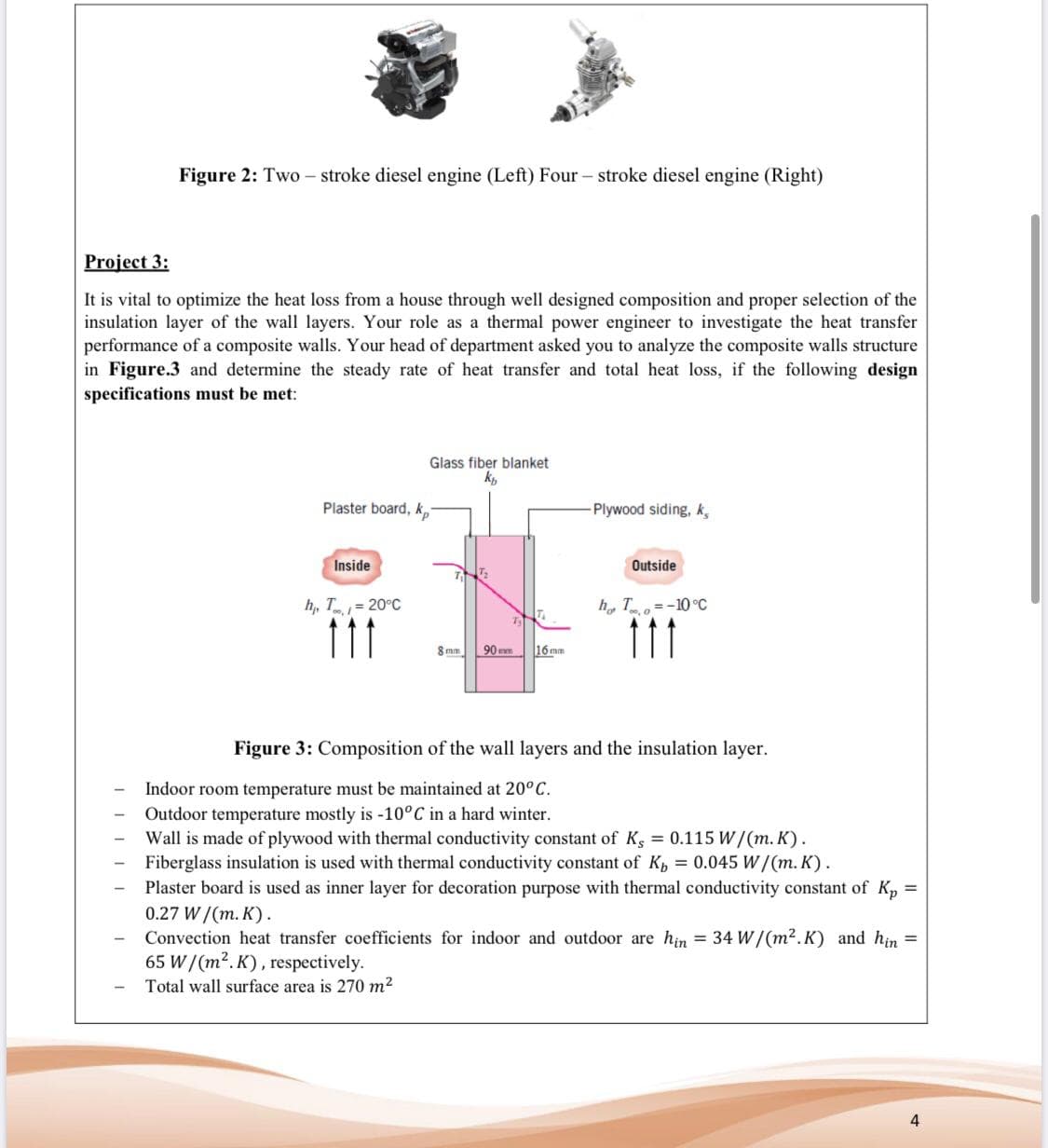
Project 3:
It is vital to optimize the heat loss from a house through well designed composition and proper selection of the
insulation layer of the wall layers. Your role as a thermal power engineer to investigate the heat transfer
performance of a composite walls. Your head of department asked you to analyze the composite walls structure
in Figure.3 and determine the steady rate of heat transfer and total heat loss, if the following design
specifications must be met:
Glass fiber blanket
kp
Plaster board, k,
Plywood siding, k,
Outside
Inside
h, T=-10 °C
h, T = 20°C
11
16 mm
90 mm
8 mm
Figure 3: Composition of the wall layers and the insulation layer.
Indoor room temperature must be maintained at 20°C.
Outdoor temperature mostly is -10°C in a hard winter.
Wall is made of plywood with thermal conductivity constant of K, = 0.115 W/(m. K).
Fiberglass insulation is used with thermal conductivity constant of K, = 0.045 W/(m. K).
Plaster board is used as inner layer for decoration purpose with thermal conductivity constant of K,
0.27 W/(m. K).
Convection heat transfer coefficients for indoor and outdoor are hin = 34 W/(m2.K) and hin =
65 W/(m². K) , respectively.
Total wall surface area is 270 m2
4
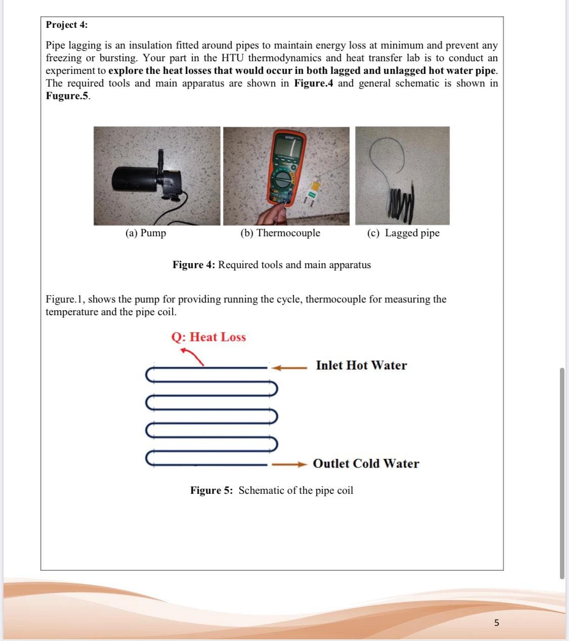
Transcribed Image Text:Project 4:
Pipe lagging is an insulation fitted around pipes to maintain energy loss at minimum and prevent any
freezing or bursting. Your part in the HTU thermodynamics and heat transfer lab is to conduct an
experiment to explore the heat losses that would occur in both lagged and unlagged hot water pipe.
The required tools and main apparatus are shown in Figure.4 and general schematic is shown in
Fugure.5.
(c) Lagged pipe
(a) Pump
(b) Thermocouple
Figure 4: Required tools and main apparatus
Figure.1, shows the pump for providing running the cycle, thermocouple for measuring the
temperature and the pipe coil.
Q: Heat Loss
Inlet Hot Water
Outlet Cold Water
Figure 5: Schematic of the pipe coil
Expert Solution
This question has been solved!
Explore an expertly crafted, step-by-step solution for a thorough understanding of key concepts.

Step by step
Solved in 6 steps with 5 images

Knowledge Booster


Learn more about
Need a deep-dive on the concept behind this application? Look no further. Learn more about this topic, mechanical-engineering and related others by exploring similar questions and additional content below.Recommended textbooks for you
Principles of Heat Transfer (Activate Learning wi…
Mechanical Engineering
ISBN:
9781305387102
Author:
Kreith, Frank; Manglik, Raj M.
Publisher:
Cengage Learning
Principles of Heat Transfer (Activate Learning wi…
Mechanical Engineering
ISBN:
9781305387102
Author:
Kreith, Frank; Manglik, Raj M.
Publisher:
Cengage Learning