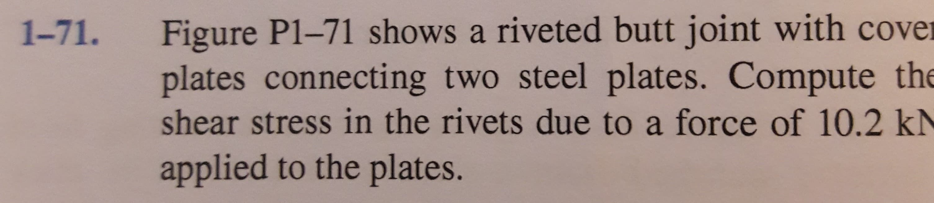
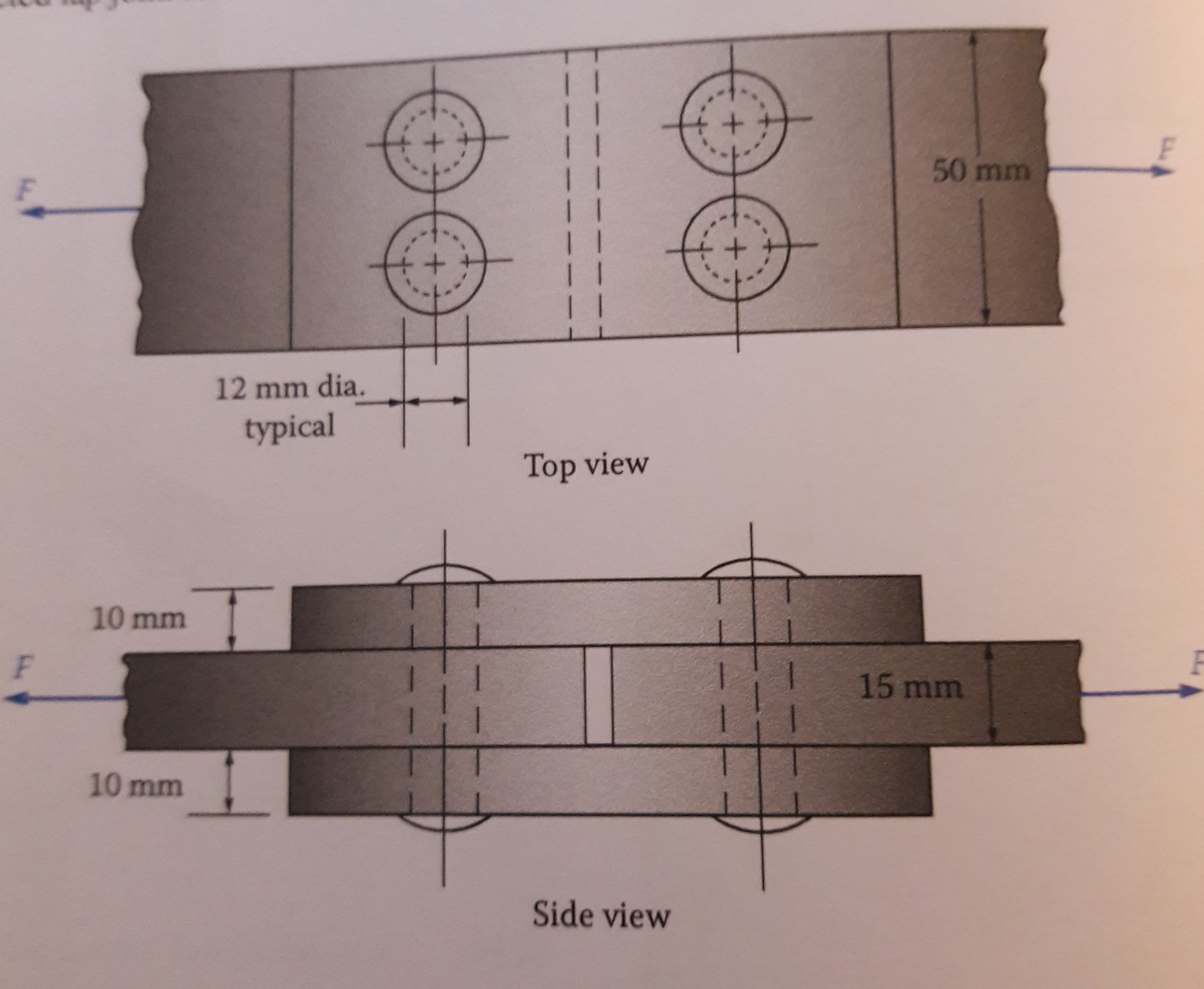
Figure P1-71 shows a riveted butt joint with cover plates connecting two steel plates. Compute the 1-71. shear stress in the rivets due to a force of 10.2 kN applied to the plates. 50 mm 12 mm dia. typical Top view 10 mm 15 mm 10 mm Side view
Q: 410 N 30° 45° 200 N 10 10 mm
A:
Q: A steel tire has a dimensions indicated in the figure below. At 78 degrees Celsius, the said tire…
A: Given: The tire width, b = 900 mm The thickness of tire, t = 12 mm The internal diameter of tire, d…
Q: Determine the nominal block shear strength of the tension member shown in Figure P3.5-2. The bolts…
A: Write the expression for shear areas and substitute the values from the given figure.
Q: 8 kN 8 kN В L 45° 45° 60° A E L D
A:
Q: The assembly in the given figure is consists of steel and aluminium bars and it is fixed at the wall…
A:
Q: Question 3-5: Truss is loaded as shown: 24 KSI in tension 18 KSI in compression Question 3 A 8 ft…
A:
Q: igure 3: Given the figure, determine the member that will be designed for maximum tension (Note:…
A:
Q: A short compression member has the cross sec- tion shown in Figure P1-55. Compute the stress in the…
A: Area of the cross-section is,
Q: A marine engine cylinder has a compression ratio (r) of 9.5, a clearance volume of 650 cm3 and a…
A:
Q: Solve the following problems: 1. A bar made of A-36 steel has the dimensions shown in Fig.3-22.lf an…
A: For A-36 steelE = 200 GPa , G = 75 GPa , μ(Poission's ratio) = 0.32σy = 250 MPa ( yield strength Acs…
Q: you can provide handwritten solution also. At a point in a material under stress, the intensity of…
A: Normal stress acting on principal plane is known as a principal stress. The plane at which no shear…
Q: A member is subjected to a major stress of 115 MPa (tensile), minor stress of 50 MPa (tensile) along…
A: Permissible stress is stress which produces due to pressure or forces which does not exceed the…
Q: Tyx Figure 1 Point A- x-direction stress 60MPA(compression), y-direction stress 40MPA(tension),…
A:
Q: The front landing gear for a mobile crane is shown in the above figure with the indicated main…
A:
Q: Figure 1 shows an element ith stresses. Angle 1 Tyx Tyx Figure 1 Point C)- x-direction stress…
A: The three basic equations to determine the stress at various cross-sections are:…
Q: S-1) Given in Figure 1; a) Find the dimensions d, b and c? b) Calculate the stresses occurring in…
A: Stress : When an object is applied an external force or moment a resistance force is setup within…
Q: A machine having a mass of 4200 kg is supported by three solid steel rods arranged as shown in…
A:
Q: 3-81: Figure P3-81 shows two rods, AB and BC, supporting a load at B. Each rod is steel and has a…
A: Given Data,
Q: Q3/ Draw 1:2 Scale, the top view and sectional front view of a double riveted lap joint with a chain…
A: solved
Q: 3-55: A ring of SAE 301 stainless steel is to be placed on a shaft having a temperature of 20…
A: Given data for SAE 301 stainless steel,
Q: Direct stresses of 120 N/mm2 (tension) and 90 N/mm2 (compression) are applied at a particular point…
A: Given data: The direct stresses in mutually perpendicular direction are σx=120 Nmm2 and σy=-90…
Q: A square bar carries a series of loads as shown in Figure P1-47. Compute the stress in each segment…
A: The forces in the member can be drawn as shown below,
Q: A steel rod 8 mm in diameter is under the action of a tensile force (P) of 600 Newton. Calculate the…
A: Tensile stress is given by the following formula, Sigma=P/A Where P is the tension force and A is…
Q: PROBLEM: A knuckle joint is used to connect two circular rods. The tensile force applied is 50 kN.…
A: First draw the free body diagram, Calculate Dpin, drod
Q: A machine having a mass of 4200 kg is supported 1-45. by three solid steel rods arranged as shown in…
A: Mass of the machine = 4200 kg = 4200*9.81 = 41202 N Diameter of the rod = 20 mm Free body diagram of…
Q: 3- A bracket, as shown in Fig., carries a load of 10 kN. Find the size of the weld if the allowable…
A: Welding is method of joining two similar or dissimilar metal with or without heat , or with or…
Q: 1-54) Figure P1-54 shows the shape of a test specimen used to measure the tensile properties of…
A: given data as per question initial diameter of bar = 3/8*2 = 0.75in final diameter in the middle of…
Q: By using the Mohr's circle approach, c. Construct the Mohr's circle for the stress element shown in…
A: Givenσx=45MPaσy=-60MPaτ=30MPa
Q: 3-67: A short post is made by welding steel plates into a square. as shown in Figure P3-67, and then…
A: Given data as per question b = 1500 mm t = 10mm axial load = 900 kN f'c = 6000 psi = 41.37 N/mm2…
Q: S-3) In order to carry the 100 KN force safely on the frame in Figure 3, find the diameters of the B…
A:
Q: Two steel plates grade 300 having the same dimensions (250mm width x 25mm depth) are joint using…
A: Given data, Applied force, F = 950 kN = 950000 N Shear strength of the bolt, τs,bolt=0.6×830=498 MPa…
Q: A pushrod in the valve mechanism of an automotive engine has a nominal length of 203 mm. If the rod…
A:
Q: For Problems 64 through 68, compute the maximum stress in the member, considering stress…
A: Given data: - The minimum width of the plate is d = 0.80 in. The maximum width of the plate is D =…
Q: 1. Determine the shear, tensile and bearing stresses for the structural connection shown in Fig. 1.…
A:
Q: The figure shows a flat hanger bar for supporting shop equipment in a factory. The bar is fixed to a…
A: Given data, Width of hanging bar, w = 1.5 in to 3 in Diameter of the bolt, d = 1 in From the…
Q: The bracket shown in Figure ST - 228 is attached to a column by 6 - 20 mm diameter bolts and loaded…
A: The bearing stress between the bolt and the bracket is 61.46 MPa.
Q: The lap joint shown in figure (3) is fastened by four 12- mm diameter rivets subjected to load P KN,…
A: Data given: External load P = 575 kN Number of rivets used in each side: 2 (total 4 reviets)…
Q: A 30 mm square is drawn on the rim of a large steel pressure vessel. The biaxial stress situation in…
A: First calculate the strain in y-direction εy using the equation. εy=σyE-νσxE Here,σx is the normal…
Q: A pushrod in the valve mechanism of an automotive engine has a nominal length of 203 mm. If the rod…
A:
Q: 3-140N Luk applied to a wrench with one hand force, the steel AB Bolt is tightened. Accordingly, the…
A: Given: F=140 N Allowable shear stress= 100 MPa
Q: At a point of a material, the stresses forming a two-dimensional system are shown in Figure Q1. By…
A: Given:σx=50 MPaσy=30 MPaζxy=20 MPa
Q: A loaded structure with a two-dimensional stress state has the stress in the x-axis is 13.5 Mpa, in…
A: A loaded structure with a two-dimensional stress state has the stress in the x-axis is 13.5 Mpa, in…
Q: Reproduce Figure 2.23 twice, first adjusting it so that it accurately depicts the case in which the…
A: For the first case, it is given that the horizontal stress is half of the vertical stress that means…
Q: 66 0.60 in. 1.60 in. 0.40 in. -0.80 in.- → Shape of a slug for Problem 1-62. FIGURE P1-62
A: Given data as per question Thickness of sheet to be punched = 0.194 in. Punching force = 45000lb
Q: The 10-mm-diameter steel bolt in (Figure 1) is surrounded by a bronze sleeve . The outer diameter of…
A: Givend0=20mmdi=10mmEst=200GpaEbt=100GpaP=15.3Kn
Q: Q-1 The attachment shown carries a static bending load of 15 kN. The attachment length, 4, is 260…
A: Static bending load acting is 15 kN Attachment length 260 mm
Q: A cylindrical bar shown in the figure below has axial loads applied as illustrated. Calculate the…
A: As per given We have to find stress in bar of section AB, BC and CA
Q: The 3/4" bolts holding the steel plates together below can withstand a maximum shear stress of 36…
A:
Trending now
This is a popular solution!
Step by step
Solved in 2 steps with 2 images
- 3-67: A short post is made by welding steel plates into a square. as shown in Figure P3-67, and then filling the area inside with concrete. Compute the stress in the steel and in the concrete if b = 1500 mm and t = 10mm, and the post carries an axial load of 900 kN. See Section 2-10 for concrete properties. Use f'c = 6000 psi.Figure 2: Given the below determine the bar force at BD. (Answer in whole number, indicate the answer in kN. just input the value, do this for all the questions on Figure 2) Note: if the member is in compression, write a negative symbol before it, ex: 12kn in compression is answer:-12Compute the maximum stress in the member, considering stress concentrations. Use Figure P3-66 2.00-in dia. 0.10-in radius 1.25-in dia. Applied torque = 2200 lb-in
- Find the Axial Forces in members 1 - 5. Find the Displacement Displacement of joint A (mm, positive right and up) for both Horizontal and VerticalCompute the stresses at A and B on the link loaded as shown in Figure P-912 if P = 9000 lb and F = 3000 lb.1-32 A control pedal for actuating a spring mechanism is shown in the figure. Calculate the shear stress in pins A and B due to force P when it causes a stress of 75 MPa in rod AB. Both pins are in double shear. Diameter of the Pin attached in the photo of the table provided below.
- A link in an automated packaging machine is a hollow tube made from 6061-T6 aluminum. Its dimensions are as follows: outside diameter = 32.0 mm, inside diameter = 28.0 mm, and length = 1.00 m. Compute the tensile force required to produce an elongation of the bar of 1.3 mm. Would the stress produced by the force just found be safe if the load is applied repeatedly?The force P3 to make it to equilibrium in kN is The Stress in section 1 in N/mm2 is The Compressive Stress in section 2 in N/mm2 is The stress in section 3 in N/mm2 is The total change in length in x10-3 mm isFigure 4: Determine the bar force at FN (Answer in whole number, indicate the answer in kN. just input the value, do this for all the questions on Figure 4) Note: if the member is in compression, write a negative symbol before it, ex: 12kn in compression is answer:-12
- 3-140N applied to a wrench tightening the steel AB bolt with one hand force. Accordingly, the safe diameter of the AB bolt Calculate its value. on the bolt ignoring the threads, turn the bolt into a solid circular accept cuts. τem =100MPa3-81: Figure P3-81 shows two rods, AB and BC, supporting a load at B. Each rod is steel and has a diameter of 10.00 mm. Compute the elongation of rods AB and BC when a load having a mass of 4200 kg is suspended from B.3-123: A round shaft has two grooves in which rings are placed to retain a gear in position, as shown in Figure P3-123. If the shaft is subjected to an axial tensile force of 36 kN, compute the maximum tensile stress in the shaft.