For the splice connection shown in the figure, Compute the design strength based on shear and bearing. (Use LRFD) The plates are PL 12" x 7" steel ASTM A36 (Fy = 36 ksi, Fu = 58 ksi) and the bolts are 7/8-in. diameter A325 (Fnu = 68 ksi) in standard holes. P₁ Pa 0 O C O 3 in 3 in 3 in 3 in 3 in | -in bolts 3 in 6 in 3 in in P₁ P 12 in
For the splice connection shown in the figure, Compute the design strength based on shear and bearing. (Use LRFD) The plates are PL 12" x 7" steel ASTM A36 (Fy = 36 ksi, Fu = 58 ksi) and the bolts are 7/8-in. diameter A325 (Fnu = 68 ksi) in standard holes. P₁ Pa 0 O C O 3 in 3 in 3 in 3 in 3 in | -in bolts 3 in 6 in 3 in in P₁ P 12 in

Steel Design (Activate Learning with these NEW titles from Engineering!)
6th Edition
ISBN:9781337094740
Author:Segui, William T.
Publisher:Segui, William T.
Chapter3: Tension Members
Section: Chapter Questions
Problem 3.5.4P

Related questions
Question
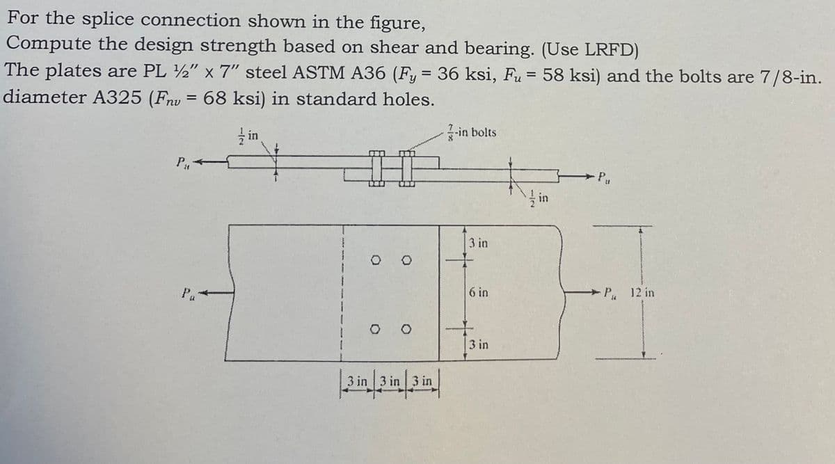
Transcribed Image Text:For the splice connection shown in the figure,
Compute the design strength based on shear and bearing. (Use LRFD)
The plates are PL 12" x 7" steel ASTM A36 (Fy = 36 ksi, Fu = 58 ksi) and the bolts are 7/8-in.
diameter A325 (Fnu = 68 ksi) in standard holes.
P₁4
in
3 in 3 in
3 in 3 in 3 in
-in bolts
3 in
6 in
+
Pu
P 12 in
Expert Solution
This question has been solved!
Explore an expertly crafted, step-by-step solution for a thorough understanding of key concepts.

Step by step
Solved in 4 steps with 3 images

Knowledge Booster


Learn more about
Need a deep-dive on the concept behind this application? Look no further. Learn more about this topic, civil-engineering and related others by exploring similar questions and additional content below.Recommended textbooks for you
Steel Design (Activate Learning with these NEW ti…
Civil Engineering
ISBN:
9781337094740
Author:
Segui, William T.
Publisher:
Cengage Learning
Steel Design (Activate Learning with these NEW ti…
Civil Engineering
ISBN:
9781337094740
Author:
Segui, William T.
Publisher:
Cengage Learning