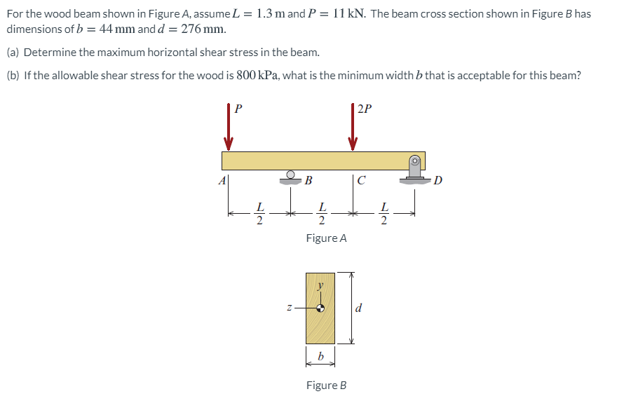
For the wood beam shown in Figure A, assume L = 1.3 m and P = 11 kN. The beam cross section shown in Figure B has dimensions of b = 44 mm and d = 276 mm. (a) Determine the maximum horizontal shear stress in the beam. (b) If the allowable shear stress for the wood is 800 kPa, what is the minimum width b that is acceptable for this beam? P | 2P B |C D Figure A d b Figure B
Q: For the loaded beam shown in Figure Q6 below, consider section M-M and detemine the following: 6.1…
A: Given Data: Length of the beam, L=0.4+0.3+0.4=1.1 m
Q: Q : A simply supported beam shown in Figure (3-A) below, has the cross section shown in figure (3-B)…
A:
Q: Design a timber glue-lam beam made from douglas fir for the given load in the figure below. 670…
A:
Q: Question 1 A simply supported composite beam 3 m long carnes a uniformly distrbuted load of…
A: Calculate the maximum bending moment.
Q: В C 3 m 3 m
A:
Q: A beam shown in Figure 6.20 is made of T beam, determine maximum bending stress in tension and…
A:
Q: |1200 Ib | 1200 Ib 3 ft R2
A: Note: As per bartelby guideline first three subpart are solved. please upload other part separately…
Q: Example 4 The simply supported beam in Figure below has a rectangular 3kN cross section 100 mm wide…
A: Given: Uniform distributed load at the beam is, w=1.5 kN/m . Point load acting at point B is 3 kN .…
Q: A simply supported beam with a length L = 11.3 ft and height 7 in. is bent by couples M0 into a…
A: GIVEN: Length (L)=11.3 ft Curvature (k)=0.003 /ft y=3.5 in TO FIND: The deflection at mid span and…
Q: Example 4 The simply supported beam in Figure below has a rectangular 3kN cross section 100 mm wide…
A: Solution: To find support reactions at A and B, considering static equilibrium,…
Q: For the wood beam shown in Figure A, assume L = 1.5 mand P = 15 kN. The beam cross section shown in…
A:
Q: Aluminum beam AB (E=10x106 psi) is simply supported as shown. Magnesium rod CD (a = 14.5 x 10⁶…
A: Given That EAl=10×106psiEMg=6.5×10⁶psiA=1in2l=12''△T=100°α=14.5×10⁻⁶in/in/°F
Q: A steel beam is built up from a W 410 x 85 wide flange beam and two 180 mm x 9 mm cover plates (see…
A: To find: The required bolt spacing in longitudinal direction. Given: The allowable load in each bolt…
Q: A wooden beam 5 m long, simply supported at its ends and it is carrying a point load of 8 kN at its…
A:
Q: Q.2) For a T section beam with twolong wooden planks whose dimensions (all in mm) are shown in…
A:
Q: The overhanging beam shown in Figure 2 is subjected to two point loads, P at the free end D and 2P…
A: NOTE:- As per our company guidelines we are supposed to answer only first 3 sub-parts. Kindly repost…
Q: Q2: Find the maximum shearing stress and the flexural stress of simply supported beam made of steel…
A: Calculation of maximum shearing shearing and flexural stress, both are two different question. As,…
Q: The cantilever beam, whose loading condition and cross-section are given in the figure, is ideal…
A:
Q: 2. A cantilever beam AB of isosceles trapezoidal cross section has length L = 0.8 m, dimensions b, =…
A: Part A) Find the maximum moment due to beams' weight.
Q: 5. A solid rectangular beam is loaded as shown in Figure Q5a. The beam is pin-supported at B and…
A:
Q: A beam ABCD rests on simple supports at B and C. The beam has a slight initial curvature so that end…
A:
Q: 3. A rectangular beam has an extended cantilever beam the is attached at the end of the beam. A…
A: As per given question We have to determine What is the angle of twist of the beam if the length of…
Q: rectangular bar having width twice the depth is used as a beam. The beam is made of mild steel…
A:
Q: The cross section of the beam shown in the figure was created by hammering 16x4 [cm.cm] and 24x4…
A: Givenσem=10MPaτem=1MPa
Q: Q1 Calculate the bending stresses at top and bottom fibers of a simply supported beam and loaded as…
A:
Q: 4. A cantilever beam with cross section shown below and span of 3 m is subjected to concentrated…
A: Given Data: The span of the beam is L = 3 m. The concentrated load acting on the beam is P at its…
Q: 6. A cantilever beam with cross section shown in Figure 4 and span of 3.6 concentrated load (P) at…
A: Givenmaximum shear stress on section τmax=4MPa
Q: A composite beam is fabricated by bolting two wooden boards (b = 3 in. and d = 12 in.) to the sides…
A:
Q: For the loaded beam shown in Figure Q6 below, consider section M-M and determine the following: 6.1…
A:
Q: For the loaded beam shown in Figure Q6 below, consider section M-M and determine the following: 6.1…
A: Solution - First we will find out the reaction force developed at points A and D Then using the…
Q: Q1 A cantilever beam AB of isosceles trapezoidal cross section has length L = 0.8 m, dimension bi =…
A: For solution refer below images.
Q: A built-in cantilever beam with a hollow rectangular cross-section is subjected to a uniformly…
A: The variation of shear force for a cantilever subjected to UDL is to be identified. Shear force…
Q: 200 kN 100 kN/m 100 kN.m 1m 1 1m 2m 3m Figure 1: An overhanging beam For the same beam and loading…
A:
Q: The iron beam with E=120 GPa as shown in Figure 2, is subjected to a moment of 600 N.m. 25 mm 150 mm…
A:
Q: 5.8-6) A cantilever beam of length L = 2 m sup- ports a load P = 8.0 kN (see figure). The beam is…
A:
Q: A cantilevered beam AB carrying a uniform load, w as shown in Figure Q2 (e). The cross section of…
A: The moment of inertia of the given section can be determined as, The value of the maximum bending…
Q: A homogeneous, prismatic beam shown in the figure has a weight of 4.7 kN/m and is carrying a…
A:
Q: A steel beam ABC carries a concentrated load of P (kN) at B and C, as shown in Figure Q3(a). The…
A: Drawing the free body diagram as shown below, ∑Fy=0VA+VB=2P∑MA=0 P×10+P×15=VB×10VB=2.5P, VA=-0.5P…
Q: beam is loaded as shown in the figure. F = 2200 lb, b = 2 in. and h = 4 in. Determine the…
A: Given data:- Force (F) =2200lb b= 2 in h=4 in
Q: 2. The cantilever beam shown in the figure below is subjected to loads P, = 3 kips and P, = 8.5…
A:
Q: Two wood box beams (beams A and B) have the same outside dimensions (200mm x 360mm) and the same…
A: Given data
Q: A beam supported by two identical springs at points A and B (see figure). Given that flexural of…
A:
Q: The beam AB, shown in Figure 1a, with length L = 4.5 m is subjected to a uniform distributed load w…
A: A beam is defined as a structural member subjected to transverse shear load during its…
Q: The iron beam with E=120 GPa as shown in Figure 2, is subjected to a moment of 600 N.m. 25 mm 150 mm…
A:
Q: For the loaded beam shown in Figure Q6 below, consider section M-M and determine th following: The…
A:
Q: A simply supported steel beam is subjected to a uniformly distributed load as shown in Figure E5.2.…
A:
Q: An overhanging beam ABCD is supported and loaded as shown in Figure 4(a). The beam cross-section as…
A:
Q: Calculate the vertical shear stress (N / cm2) at point A in the critical section of the beam below…
A: Please refer to the detailed attached solution:
Q: 3. An aircraft floor beam is made of a 100" length of extruded aluminum with Ftu=76 ksi, Fsu=60 ksi,…
A: Maximum shear stress in the section . ∵t1≠t3 t1=t2 and W1=W2 T=220 in-lb CCW h'=h-t12-t22…
Q: Beam AB is subjected to a distributed load as shown in (Figure 1). The cross section of the beam is…
A: Given: The load w is 80 kN/m for the beam as shown below: The cross section dimension is shown…
Trending now
This is a popular solution!
Step by step
Solved in 3 steps with 2 images
- A simply supported wooden I-beam with a 12-ft span supports a distributed load of intensity q = 90 lb/ft over its length (see figure part a). The beam is constructed with a web of Douglas-fir plywood and flanges of pine glued to the web, as shown in the figure part b. The plywood is 3/8 in. thick: the flanges are 2 in, × 2 in, (actual size). The modulus of elasticity for the plywood is 1,600,000 psi and for the pine is 1,200,000 psL Calculate the maximum bending stresses in the pine flanges and in the plywood web. What is q, if allowable stresses are 1600 psi in the flanges and 1200 psi in the web?Two wood beams, each of rectangular cross section (3.0 in. x 4.0 in., actual dimensions), are glued together to form a solid beam with dimensions 6.0 in. x 4.0 in. (sec figure). The beam is simply supported with a span of S ft. What is the maximum moment Mmaxthat may be applied at the left support if the allowable shear stress in the glued joint is 200 psi? (Include the effects of the beams own weight, assuming that the wood weighs 35 lb/ft3.) Repeat part (a) if Mmaxis based on allowable bending stress of 2500 psi.A hollow box beam is constructed with webs of Douglas-fir plywood and flanges of pine, as shown in the figure in a cross-sectional view. The plywood is 1 in. thick and 12 in. wide; the flanges are 2 in. × 4 in. (nominal size). The modulus of elasticity for the plywood is 1,800,000 psi and for the pine is 1,400,000 psi. If the allowable stresses are 2000 psi for the plywood and 1750 psi for the pine, find the allowable bending moment Mmaxwhen the beam is bent about the z axis. Repeat part (a) if the beam is now bent about its y-axis.
- The cross section of a sand wie h beam consisting of aluminum alloy faces and a foam core is shown in the figure. The width b of the beam is 8.0 in, the thickness I of the faces is 0.25 in., and the height hcof the core is 5.5 in. (total height h = 6.0 in). The moduli of elasticity are 10.5 × 10⁶ psi for the aluminum faces and 12.000 psi for the foam core. A bending moment M = 40 kip-in. acts about the z axis. Determine the maximum stresses in the faces and the core using (a) the general theory for composite beams and (b) the approximate theory for sandwich beams.-14 A simply supported composite beam with a 3.6 m span supports a triangularly distributed load of peak intensity q0at mid-span (see figure part a). The beam is constructed of two wood joists, each 50 mm x 280 mm, fastened to two steel plates, one of dimensions 6 mm × 80 mm and the lower plate of dimensions 6 mm x 120mm (see figure part b). The modulus of elasticity for the wood is 11 GPa and for the steel is 210 GPa. If the allowable stresses are 7 MPa for the wood and 120 MPa for the steel, find the allowable peak load intensity q0maxwhen the beam is bent about the z axis. Neglect the weight of the beam.A cantilever beam of length L = 2 m supports a load P = 8,0 kN (sec figure). The beam is made of wood with cross-sectional dimensions 120 mm x 200 mm. Calculate the shear stresses due to the load/"at points located 25 mm, 50 mm, 75 mm, and 100 mm from the top surface of the beam. From these results, plot a graph showing the distribution of shear stresses from top to bottom of the beam.
- A bimetallic beam used in a temperature-control switch consists of strips of aluminum and copper bonded together as shown in the figure, which is a cross-sectional view. The width of the beam is LO in,, and each strip has a thickness of 1/16 in. Under the action of a bending moment M = 12 lb-in, acting about the z axis, what are the maximum stresses aaand ecin the aluminum and copper, respectively? (Assume fA, = 10,5 x l0 psi and ecu= 16,8 × 10⁶ psi,)A steel plate (called a cover ploie) having cross-sectional dimensions 6,0 in. × 0.5 in. is welded along the full length of the bottom flange of a W 12 × 50 wide-flange beam (sec figure, which shows the beam cross section). What is the percent increase in the smaller section modulus (as compared to the wide-flange beam alone)?A W 12 x 50 steel wide-flange beam and a segment of a 4-inch thick concrete slab (see figure) jointly resist a positive bending moment of 95 kip-ft. The beam and slab are joined by shear connectors that are welded to the steel beam. (These connectors resist the horizontal shear at the contact surface.) The moduli of elasticity of the steel and the concrete are in the ratio 12 to 1. Determine the maximum stresses r1 and xtin the steel and concrete, respectively. Note: See Table F-l(a) of Appendix F for the dimensions and properties of the steel beam.
- A cantilever beam AB with a circular cross section and length L = 750 mm supports a load P = 800 N acting at the free end (see figure). The beam is made of steel with an allowable bending stress of 120 MPa. Determine the required diameter dmm(figure part a) of the beam, considering the effect of the beam's own weight. Repeat part (a) if the beam is hollow with wall thickness t = df$ (figure part b); compare the cross-sectional areas of the two designs.Two flat beams AB and CD, lying in horizontal planes, cross at right angles and jointly support a vertical load P at their midpoints (see figure). Before the load P is applied, the beams just touch each other. Both beams are made of the same material and have the same widths. Also, the ends of both beams are simply supported. The lengths of beams AB and CD are LABand LCD, respectively. What should be the ratio tABltCDof the thicknesses of the beams if all four reactions arc to be the same?The cross section of a rectangular beam having a width b and height h is shown in part a of the figure. For reasons unknown to the beam designer, it is planned to add structural projections of width b/9 and height d/9 the top and bottom of the beam (see part b of the figure). For what values of d is the bending-moment capacity of the beam increased? For what values is it decreased?