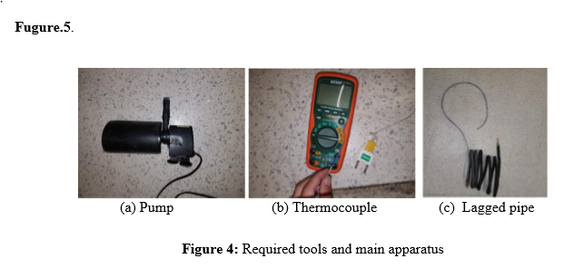
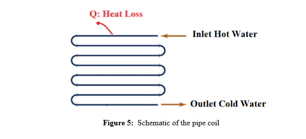
Fugure.5. (a) Pump (c) Lagged pipe (b) Thermocouple Figure 4: Required tools and main apparatus Q: Heat Loss Inlet Hot Water Outlet Cold Water Figure 5: Schematic of the pipe coil


Project 4:
Pipe lagging is an insulation fitted around pipes to maintain energy loss at minimum and prevent any freezing or bursting. Your part in the HTU
Figure.1, shows the pump for providing running the cycle, thermocouple for measuring the temperature and the pipe coil.
Your lab instructor asked you to perform the following tasks:
• Fit the lagging around the pipe
• Connect the pump to inlet of coil
• Measure the hot water terampere at the inlet (make sure the temperature reaches its steady state before measuring it)
• Operate the cycle by turn on the pump
• Measure the cold water terampere at the outlet in steady state.
• Repeat the previous step with unlagged pipe
• Search for an appropriate video where a test to measure the heat loss through unlagged and lagged pipe is conducted.
After completion of the previous you are required to answer the following:
1. Define the terminology pipe lagging with aid of schematics
2. Explore the main difference between lagged and unlagged pipe, and explore the heat loss through both pipes (no more than 120)
3. Is it necessary to increase the insulation thickness to approach better lagging? If not explain your answer with aid of schematics and mathematical explanation


Trending now
This is a popular solution!

Step by step
Solved in 3 steps with 2 images


