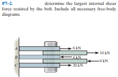
P7-2. force resisted by the bolt. Include all necessary free-body diagrams. determine the largest internal shear 6 kN + 10 kN 8 kN 20 kN


Q: 7-11. The overhang beam is subjected to the uniform distributed load having an intensity of w = 50…
A:
Q: F7-3. Determine the internal normal force, shear force, and bending moment at point C in the beam.…
A: Draw the FBD of the given problem. Apply equilibrium condition. Determine the moment about point B.
Q: P7-3. Determine the largest internal normal force in the bar. D. 10 kN 5 kN 2 kN 6 kN
A: Determine the normal force in the bar: Apply the conditions of the equilibrium: Where, FX is the…
Q: 20 KNIM 48KN m
A: given
Q: R12-2. The T-beam is subjected to a shear of V = 150 kN. Determine the amunt of this force that is…
A: Given data: The vertical force is V=150 kN. The sectional diagram for the above beam is:…
Q: 7-26. The beam is made from three boards glued together at the seams A and B. If it is subjected to…
A:
Q: P7-2. determine the largest internal shear force resisted by the bolt. Include all necessary…
A: Consider the free body diagram of the middle panel as shown below. The 6 kN force is balanced by…
Q: F7-15. Determine the maximum average shear stress developed in each 12-mm-diameter bolt. 10 kN 5 kN…
A: Given that →Load=10 KN dia=12 mm=0.012 m
Q: F7-9. The boards are bolted together to form the built-up beam. If the beam is subjected to a shear…
A: Find the spacing of the bolts.
Q: 7-22. Determine the resultant internal loadings acting on the cross section at point E. The load D…
A: Draw the free body diagram for a better understanding of the given problem.
Q: F7-5. Determine the internal normal force, shear force, and bending moment at point Cin the beam. 5…
A: Free body diagram of the beam is given as, On using equilibrium of forces in a horizontal…
Q: F7-1. Determine the internal normal force, shear force, and bending moment at point C in the beam.…
A: Determine reactions at A and B
Q: The aluminum strut is 10 mm thick and has the cross section shown. If it is subjected to a shear of…
A: Given data: The thickness of the strut is; t = 10 mm. The magnitude of the shear load is; V = 150 N.…
Q: The aluminum strut is 10 mm thick and has the cross section shown. If it is subjected to a shear of…
A:
Q: R7-2. The long bolt passes through the 30-mm-thick plate. If the force in the bolt shank is 8 kN,…
A: Given data as per question Thickness of plate = 30 mm Force applied = 8 KN
Q: P7-6. The single-V butt joint transmits the force of 5 kN from one bar to the other. Determine the…
A: Given data The joint type is: Single-V butt joint Force transfer from the bar: 5 kN Adding the…
Q: F7-2. Determine the internal normal force, shear force, and bending moment at point Cin the beam.…
A: Shear force at any section is the summation of all shear forces acting on either side of that…
Q: 120 kN/m The B: D. res 2.2 m- - 2.2 m -2.4 m- FIG. P4.19
A:
Q: The aluminum strut is 10 mm thick and has the cross section shown. If it is subjected to a shear of…
A: Given data V=150 N
Q: *7-4. Determine the resultant internal loadings on the cross section at point D. 1.25 kN/m -1.5 m…
A: The free body diagram of the section ADEB is, Here, P is the effective loading due to the UDL. H…
Q: 12-10. If the applied shear force V= 90 kN, determine the maximum shear stress in the member. 75 mm…
A: The maximum shear stress occurs at the neutral axis (NA). Thus the maximum shear stress in the…
Q: F7-18. Draw the shear and moment diagrams for the beam. 9 kN/m А 3 m 3 m F7-18
A:
Q: The pump operates using the motor that has a power of 85 W. If the impeller at B is turning at 150…
A: Given data as per the question Operating power = 85 w diameter of shaft =20 mm ω = 150 revmin we…
Q: The overhang beam is made of 2014-T6 aluminum. If the 75-kg block has a speed of = 3 m>s at h =…
A: Modulus of elasticity (E) for 2014-T6 aluminium = 72.4 GPa h = 0.75 m v = 3 m/s m = 75 kg L = AB = 4…
Q: Determine the normal force, shear force, and moment at a section passing through point C. Take P = 8…
A:
Q: *10-4 The link acts as part of the elevator control for a small airplane. If the attached aluminum…
A: Given Data: Applied force is F = 600 N. Distance between the forces is r = 75 mm + 75 mm =150 mm.…
Q: P1: (a) Determine the internal shear force and bending moment in member BCDE immediately to the left…
A: For equilibrium of AC ΣM@A = 0 = Rc x Lac – 600 = 0 Rc = 600/5 = 120lb For equilibrium of BCDE ΣM@E…
Q: 7-42. If P- 15 kN, determine the average shear stress in the pins at A, B, and C. All pins are in…
A: As per given condition∑Fx=0Ax-FBCcos 30°=0but here FBC not…
Q: 7-21. Determine the resultant internal loadings acting on the cross section at point C in the beam.…
A: Given, The mass of load D, m=300 kg The radius of the pulley, r= 0.1 m Now free body diagram of the…
Q: Determine the location e of the shear center, point O, for the thin-walled member. The member…
A: Given: To find the shear center of the given section
Q: *7-28. Determine the normal force. shear force, and moment at sections passing through points E and…
A: Given data as per question Moment applied between Point A and E =35 N.m considering FBD of the…
Q: Determine (approximately) the internal moment and shear at the ends of each member of the portal…
A: Draw the free body diagram for the above problem.
Q: Q1- Determine the normal force Nc, the shear force Vc, and the moment Mc at point C. Assume the beam…
A:
Q: F7-14. The frame supports the loading shown. The pin at A has a diameter of 50 mm. If it is…
A: Free body diagram of the frame is shown in figure. Taking Moments around B, (clockwise positive) PAx…
Q: F7-18. Determine the maximum average shear stress developed in the 30-mm-diameter pin. 30 kN 40 kN
A: Given data: The diameter of pin, dpin = 30 mm. Calculate the resultant force as follows: R=30…
Q: R12-7. The beam supports a vertical shear of V = 35KN. Determine the resultant force this develops…
A: V = 35 kN Moment of inertia about a centroidal axis, from tables I = 5.9584 x 10⁻⁵ m4 t = 12 mm Area…
Q: The two identical boards are bolted together to form the beam. Determine the maximum spacing s of…
A: Given,shear strength(F)=15KN=15×103 NShear force(V)=50 KN=50×103 NNow moment of inertia(I) of cross…
Q: The plastic tube is subjected to a torque of 150 N # m. Determine the average shear stress in the…
A: Torque=150 N-m =150×103 N-mm ; mean dimension (a) =200 mm ; thickness (t)=3 mm ;…
Q: 7-LA Delermine the maximum shear stress in the strut if IL subjocted to a shear force of V= 20 KN.…
A:
Q: *R7-4. The circular punch B exerts a force of 2 kN on the top of the plate A. Determine the average…
A: Given data: Force exerted by the punch on the plate, P = 2 kN. The diameter of the punch, d = 4 mm.…
Q: *11-20. The smooth pin is supported by two leaves A and B and subjected to a compressive load of 0.4…
A: Draw the diagram of a loaded smooth pin, Apply force equilibrium in a vertical direction and…
Q: F7-5. Determine the internal normal force, shear force, and bending moment at point C in the beam. 5…
A:
Q: can you solve this?
A: Draw the free-body diagram of the beam.
Q: •7-1. If the wide-flange beam is subjected to a shear of V = 20 kN, determine the shear stress on…
A: Given Shear stress = 20 kN Find Stress component at the mid point
Q: Determine the normal force, shear force, and bending moment at point C of the member below.
A:
Q: 7-46. The beam is subjected to a shear of V = 800 N. Determine the average shear stress developed in…
A: Draw the cross section of the given section.
Q: *7-48. Draw the shear and moment diagrans for the beam. 1.5 KN/m 2 m 3 in sp Prob. 7-48
A:
Q: 7-9. Determine the largest shear force Vthat the member can sustain if the allowable shear stres is…
A:
Q: F7-17 The strut is glued to the horizontal member at surface AB.If the strut has a thickness of 25…
A:
Q: P7-4. Determine the internal normal force at section A if the rod is subjected to the external…
A: givenexternal uniformally distributed load W=8kN/mlength of cantilever beam L=5mbeam shown as below…


Trending now
This is a popular solution!

Step by step
Solved in 3 steps with 5 images

- The A-36 steel bar consists of two segments, one ofcircular cross section of radius r, and one of square crosssection. If the bar is subjected to the axial loading of P,determine the dimensions a of the square segment so thatthe strain energy within the square segment is the same asin the circular segment.The W24 * 104 A-36 steel beam is used to support the uniform distributed load and a concentrated force which is applied at its end. If the force acts at an angle with the vertical as shown, determine the horizontal and vertical displacement at A.The copper pipe has an outer diameter of 3 in. and an inner diameter of 2.50 in. If it is tightly secured to the wall at C and it is subjected to the uniformly distributed torque along its entire length, determine the absolute maximum shear stress in the pipe. Discuss the validity of this result.
- The rigid bar is supported by the two short white spruce wooden posts and a spring. If each of the posts has an unloaded length of 1 m and a cross-sectional area of 600 mm2, and the spring has a stiffness of k = 2 MN >m and an unstretched length of 1.02 m, determine the vertical displacement of A and B after the load is applied to the bar.The observation cage C has a weight of 250 kip and through a system of gears, travels upward at constant velocity along the A-36 steel column, which has a height of 200 ft. The column has an outer diameter of 3 ft and is made from steel plate having a thickness of 0.25 in. Neglect the weight of the column, and determine the average normal stress in the column at its base, B, as a function of the cage’s position y. Also, determine the displacement of end A as a function of y.‘The frame supports the loading shown. The pin at A has a diameter of 0.25 in. If it is subjected to double shear, determine the average shear stress in the pin.
- The plastic tube is subjected to a torque of 150 N # m. Determine the average shear stress in the tube if the mean dimension a = 200 mm. Each side has a thickness of t = 3 mm.The man has a mass of 100 kg and center of mass at G. If he holds himself in the position shown, determine the maximum tensile and compressive stress developed in the curved bar at section a–a. He is supported uniformly by twobars, each having a diameter of 25 mm. Assume the floor is smooth. Use the curved-beam formula to calculate the bending stress.The short concrete cylinder having a diameter of 50 mm is subjected to a torque of 500 N # m and an axial compressive force of 2 kN. Determine if it fails according to the maximum normal stress theory. The ultimate stress of the concrete is sult = 28 MPa.
- the solid steel sheft DF has a diameter of 25 mm and is supported by smooth bearings at D and E. It is coupled to a motor at F. which delivers 12kw of bower to the shift while turning at 50 rev/s if gears A ,B and C remove 3kw,4kw,5kw respectively . determine the maximum shear stress developed in the shift within Regions CF and BC. the shaft is free to turn in its support bearings D and FThe shaft has an outer diameter of 100 mm and an inner diameter of 80 mm. If it is subjected to the three torques, determine the absolute maximum shear stress in the shaft. The smooth bearings A and B do not resist torque.The railcar docklight is supported by the 1 8-in.-diameter pin at A. If the lamp weighs 4 lb, and the extension arm AB has a weight of 0.5 lb>ft, determine the average shear stress in the pin needed to support the lamp. Hint: The shear force in the pin is caused by the couple moment required for equilibrium at A.