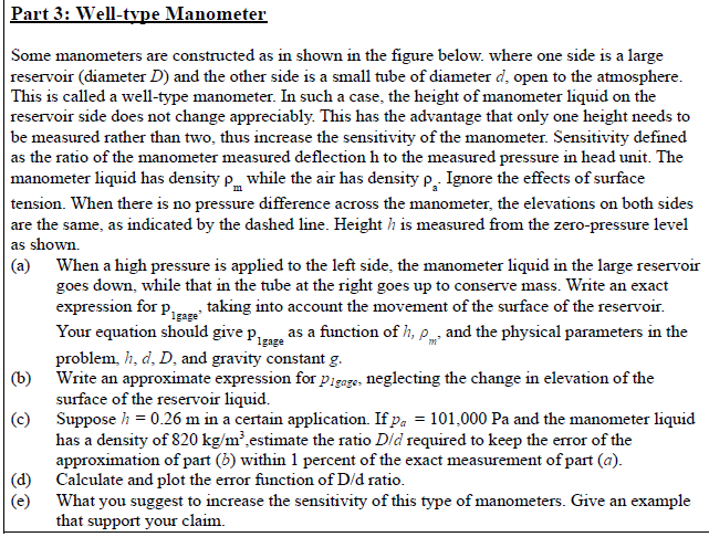
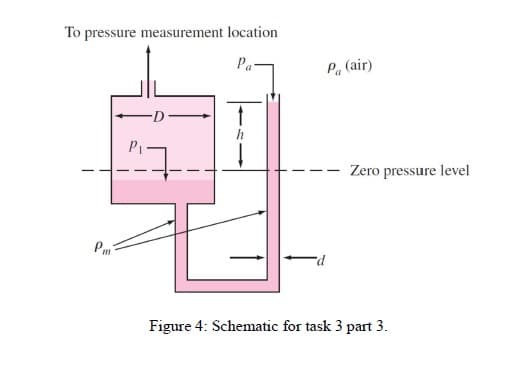
Part 3: Well-type Manometer Some manometers are constructed as in shown in the figure below. where one side is a large reservoir (diameter D) and the other side is a small tube of diameter d, open to the atmosphere. This is called a well-type manometer. In such a case, the height of manometer liquid on the reservoir side does not change appreciably. This has the advantage that only one height needs to be measured rather than two, thus increase the sensitivity of the manometer. Sensitivity defined as the ratio of the manometer measured deflection h to the measured pressure in head unit. The manometer liquid has density p while the air has density p, Ignore the effects of surface tension. When there is no pressure difference across the manometer, the elevations on both sides are the same, as indicated by the dashed line. Height h is measured from the zero-pressure level as shown. (a) When a high pressure is applied to the left side, the manometer liquid in the large reservoir goes down, while that in the tube at the right goes up to conserve mass. Write an exact expression for p taking into account the movement of the surface of the reservoir. Your equation should give proze as a function of h, p and the physical parameters in the problem, h, d, D, and gravity constant g. (b) Write an approximate expression for pigage, neglecting the change in elevation of the surface of the reservoir liquid. (c) Suppose h = 0.26 m in a certain application. If pa = 101,000 Pa and the manometer liquid has a density of 820 kg/m²,estimate the ratio Dld required to keep the error of the approximation of part (b) within 1 percent of the exact measurement of part (a). |(d) Calculate and plot the error function of D/d ratio. (e) Igage What you suggest to increase the sensitivity of this type of manometers. Give an example that support your claim. To pressure measurement location Pa- Pa (air) Zero pressure level Pm P- Figure 4: Schematic for task 3 part 3.
Part 3: Well-type Manometer Some manometers are constructed as in shown in the figure below. where one side is a large reservoir (diameter D) and the other side is a small tube of diameter d, open to the atmosphere. This is called a well-type manometer. In such a case, the height of manometer liquid on the reservoir side does not change appreciably. This has the advantage that only one height needs to be measured rather than two, thus increase the sensitivity of the manometer. Sensitivity defined as the ratio of the manometer measured deflection h to the measured pressure in head unit. The manometer liquid has density p while the air has density p, Ignore the effects of surface tension. When there is no pressure difference across the manometer, the elevations on both sides are the same, as indicated by the dashed line. Height h is measured from the zero-pressure level as shown. (a) When a high pressure is applied to the left side, the manometer liquid in the large reservoir goes down, while that in the tube at the right goes up to conserve mass. Write an exact expression for p taking into account the movement of the surface of the reservoir. Your equation should give proze as a function of h, p and the physical parameters in the problem, h, d, D, and gravity constant g. (b) Write an approximate expression for pigage, neglecting the change in elevation of the surface of the reservoir liquid. (c) Suppose h = 0.26 m in a certain application. If pa = 101,000 Pa and the manometer liquid has a density of 820 kg/m²,estimate the ratio Dld required to keep the error of the approximation of part (b) within 1 percent of the exact measurement of part (a). |(d) Calculate and plot the error function of D/d ratio. (e) Igage What you suggest to increase the sensitivity of this type of manometers. Give an example that support your claim. To pressure measurement location Pa- Pa (air) Zero pressure level Pm P- Figure 4: Schematic for task 3 part 3.

International Edition---engineering Mechanics: Statics, 4th Edition
4th Edition
ISBN:9781305501607
Author:Andrew Pytel And Jaan Kiusalaas
Publisher:Andrew Pytel And Jaan Kiusalaas
Chapter8: Centroids And Distributed Loads
Section: Chapter Questions
Problem 8.90P: The hemispherical glass bowl is filled with water. Find the location y of the center of gravity of...

Related questions
Question
I need (d and e)
Transcribed Image Text:Part 3: Well-type Manometer
Some manometers are constructed as in shown in the figure below. where one side is a large
reservoir (diameter D) and the other side is a small tube of diameter d, open to the atmosphere.
This is called a well-type manometer. In such a case, the height of manometer liquid on the
reservoir side does not change appreciably. This has the advantage that only one height needs to
be measured rather than two, thus increase the sensitivity of the manometer. Sensitivity defined
as the ratio of the manometer measured deflection h to the measured pressure in head unit. The
manometer liquid has density p while the air has density p, Ignore the effects of surface
tension. When there is no pressure difference across the manometer, the elevations on both sides
are the same, as indicated by the dashed line. Height h is measured from the zero-pressure level
as shown.
(a) When a high pressure is applied to the left side, the manometer liquid in the large reservoir
goes down, while that in the tube at the right goes up to conserve mass. Write an exact
expression for p taking into account the movement of the surface of the reservoir.
Your equation should give proze as a function of h, p and the physical parameters in the
problem, h, d, D, and gravity constant g.
(b) Write an approximate expression for pigage, neglecting the change in elevation of the
surface of the reservoir liquid.
(c) Suppose h = 0.26 m in a certain application. If pa = 101,000 Pa and the manometer liquid
has a density of 820 kg/m²,estimate the ratio Dld required to keep the error of the
approximation of part (b) within 1 percent of the exact measurement of part (a).
|(d) Calculate and plot the error function of D/d ratio.
(e)
Igage
What you suggest to increase the sensitivity of this type of manometers. Give an example
that support your claim.
Transcribed Image Text:To pressure measurement location
Pa-
Pa (air)
Zero pressure level
Pm
P-
Figure 4: Schematic for task 3 part 3.
Expert Solution
This question has been solved!
Explore an expertly crafted, step-by-step solution for a thorough understanding of key concepts.

This is a popular solution!

Trending now
This is a popular solution!

Step by step
Solved in 3 steps with 3 images

Follow-up Questions
Read through expert solutions to related follow-up questions below.
Knowledge Booster


Learn more about
Need a deep-dive on the concept behind this application? Look no further. Learn more about this topic, mechanical-engineering and related others by exploring similar questions and additional content below.Recommended textbooks for you
International Edition---engineering Mechanics: St…
Mechanical Engineering
ISBN:
9781305501607
Author:
Andrew Pytel And Jaan Kiusalaas
Publisher:
CENGAGE L

Refrigeration and Air Conditioning Technology (Mi…
Mechanical Engineering
ISBN:
9781305578296
Author:
John Tomczyk, Eugene Silberstein, Bill Whitman, Bill Johnson
Publisher:
Cengage Learning
International Edition---engineering Mechanics: St…
Mechanical Engineering
ISBN:
9781305501607
Author:
Andrew Pytel And Jaan Kiusalaas
Publisher:
CENGAGE L
Refrigeration and Air Conditioning Technology (Mi…
Mechanical Engineering
ISBN:
9781305578296
Author:
John Tomczyk, Eugene Silberstein, Bill Whitman, Bill Johnson
Publisher:
Cengage Learning