Print Reading for Industry 212 Class Date Name Industry Print Exercise 10-2 Refer to the print PR 10-2 and answer the questions below. 1. The basic depth of this part is .715. What is the tolerance on that dimension? 2. In the auxiliary section view, there is a chamfer note. What is the tolerance on the chamfer? 3. The central, smallest hole has a target size of .1577". What is the tolerance on that hole? 4. What is the maximum material condition of the largest body diameter of this part? 5. What is the angular tolerance for angles, unless otherwise specified? 6. What is the tolerance for three-place decimal values, unless otherwise specified? Review questions based on previous units: 7. Are there any hidden lines shown on this drawing? 8. What is the name of this part? 9. What scale are the views on the original drawing? 10. Is Section B-B shown in alignment with other views or as a removed view? 11. What thread class is designated for the four small holes? 12. How many cutting planes are indicated? 13. Does this drawing feature any auxiliary views?. 14. Are there any reference dimensions on this print? 15. As dimensioned, does this drawing follow the cylinder rule? OYM 94112 4 Unless Otherwise Specifed Tolerence Fraction 2 Place 3 Place Inch (Metric] = t.015 t.38] .010 t.25] t.005 (t.13] +1° Angle Do Not Scale Drawing Dimenslons & Tolerance Are In Accordance With ASME Y14.5-1994 Using The Inch System - .715± .003 A 0.0005 118 4X HOLES MUST OPEN INTO 4-40 TAPPED HOLES 30°- .076 074 2X.010 CORNER BREAK- .62 .035 - 446 030 X 45 CHAMFER 407 (R.512) .100 R.359 ON ECC R.464 ON ECC. B 2X R- .1579 D575 TARGET Ø.1577 A 0.0005/.250 A .03X45 1.497 1.503 P1.500 0395 468 CHAMFER 431 Ø.340 ECC. B 1.403 P1.400 D(.969) R.03 400 544 R- 424 389 20 R.02 (445) l.500) B .375 +.003 .500-001 4X 4-40 UNC-2BV 0.32 MIN. - 1.379 1.375 1.323 2X R.099 CONCENTRIC- WITH 100 WIDE SLOT SEE NOTE 3- R.282 312 -.197 3X R.020 MAX. 2X R.020 MAX. .19 A 440 417- 562- -.47 640 TO BOTTOM OF Ø.375 SECTION A-A NOTES: 1. BREAK ALL SHARP CORNERS WHERE POSSIBLE 2. APPLICATIONS: (.380) TAP DRILL DEPTH 3. ALL POINTS LYING WITHIN THE Ø.969 MUST BE FLUSH TO 0005 BELOW (CONCAVE) THE PLANE DEFINED BY THE AREA BETWEEN ø.969 AND Ø1.377 4X .02/.03 X 30 4. UNLESS OTHERWISE NOTED, FEATURES SHOWN ON SHALL BE TO WITHIN+.005 CHAMFER Part No INLET PORTING PLATE Part Name SECTION B-B Scale 2:1 Material Check By Date Drawn By Disk # Rev # Rel C PR ECO# Change No. bo 00 C 00-9A bodomedt 5rt ehbege etoousolotr Goodheart-Willcox Publish
Print Reading for Industry 212 Class Date Name Industry Print Exercise 10-2 Refer to the print PR 10-2 and answer the questions below. 1. The basic depth of this part is .715. What is the tolerance on that dimension? 2. In the auxiliary section view, there is a chamfer note. What is the tolerance on the chamfer? 3. The central, smallest hole has a target size of .1577". What is the tolerance on that hole? 4. What is the maximum material condition of the largest body diameter of this part? 5. What is the angular tolerance for angles, unless otherwise specified? 6. What is the tolerance for three-place decimal values, unless otherwise specified? Review questions based on previous units: 7. Are there any hidden lines shown on this drawing? 8. What is the name of this part? 9. What scale are the views on the original drawing? 10. Is Section B-B shown in alignment with other views or as a removed view? 11. What thread class is designated for the four small holes? 12. How many cutting planes are indicated? 13. Does this drawing feature any auxiliary views?. 14. Are there any reference dimensions on this print? 15. As dimensioned, does this drawing follow the cylinder rule? OYM 94112 4 Unless Otherwise Specifed Tolerence Fraction 2 Place 3 Place Inch (Metric] = t.015 t.38] .010 t.25] t.005 (t.13] +1° Angle Do Not Scale Drawing Dimenslons & Tolerance Are In Accordance With ASME Y14.5-1994 Using The Inch System - .715± .003 A 0.0005 118 4X HOLES MUST OPEN INTO 4-40 TAPPED HOLES 30°- .076 074 2X.010 CORNER BREAK- .62 .035 - 446 030 X 45 CHAMFER 407 (R.512) .100 R.359 ON ECC R.464 ON ECC. B 2X R- .1579 D575 TARGET Ø.1577 A 0.0005/.250 A .03X45 1.497 1.503 P1.500 0395 468 CHAMFER 431 Ø.340 ECC. B 1.403 P1.400 D(.969) R.03 400 544 R- 424 389 20 R.02 (445) l.500) B .375 +.003 .500-001 4X 4-40 UNC-2BV 0.32 MIN. - 1.379 1.375 1.323 2X R.099 CONCENTRIC- WITH 100 WIDE SLOT SEE NOTE 3- R.282 312 -.197 3X R.020 MAX. 2X R.020 MAX. .19 A 440 417- 562- -.47 640 TO BOTTOM OF Ø.375 SECTION A-A NOTES: 1. BREAK ALL SHARP CORNERS WHERE POSSIBLE 2. APPLICATIONS: (.380) TAP DRILL DEPTH 3. ALL POINTS LYING WITHIN THE Ø.969 MUST BE FLUSH TO 0005 BELOW (CONCAVE) THE PLANE DEFINED BY THE AREA BETWEEN ø.969 AND Ø1.377 4X .02/.03 X 30 4. UNLESS OTHERWISE NOTED, FEATURES SHOWN ON SHALL BE TO WITHIN+.005 CHAMFER Part No INLET PORTING PLATE Part Name SECTION B-B Scale 2:1 Material Check By Date Drawn By Disk # Rev # Rel C PR ECO# Change No. bo 00 C 00-9A bodomedt 5rt ehbege etoousolotr Goodheart-Willcox Publish

Welding: Principles and Applications (MindTap Course List)
8th Edition
ISBN:9781305494695
Author:Larry Jeffus
Publisher:Larry Jeffus
Chapter20: Shop Math And Weld Cost
Section: Chapter Questions
Problem 24R: What is a dimensioning tolerance?

Related questions

Question
I need questions 8, 9, and 10 answered pertaining to the print provided below.
Transcribed Image Text:Print Reading for Industry
212
Class
Date
Name
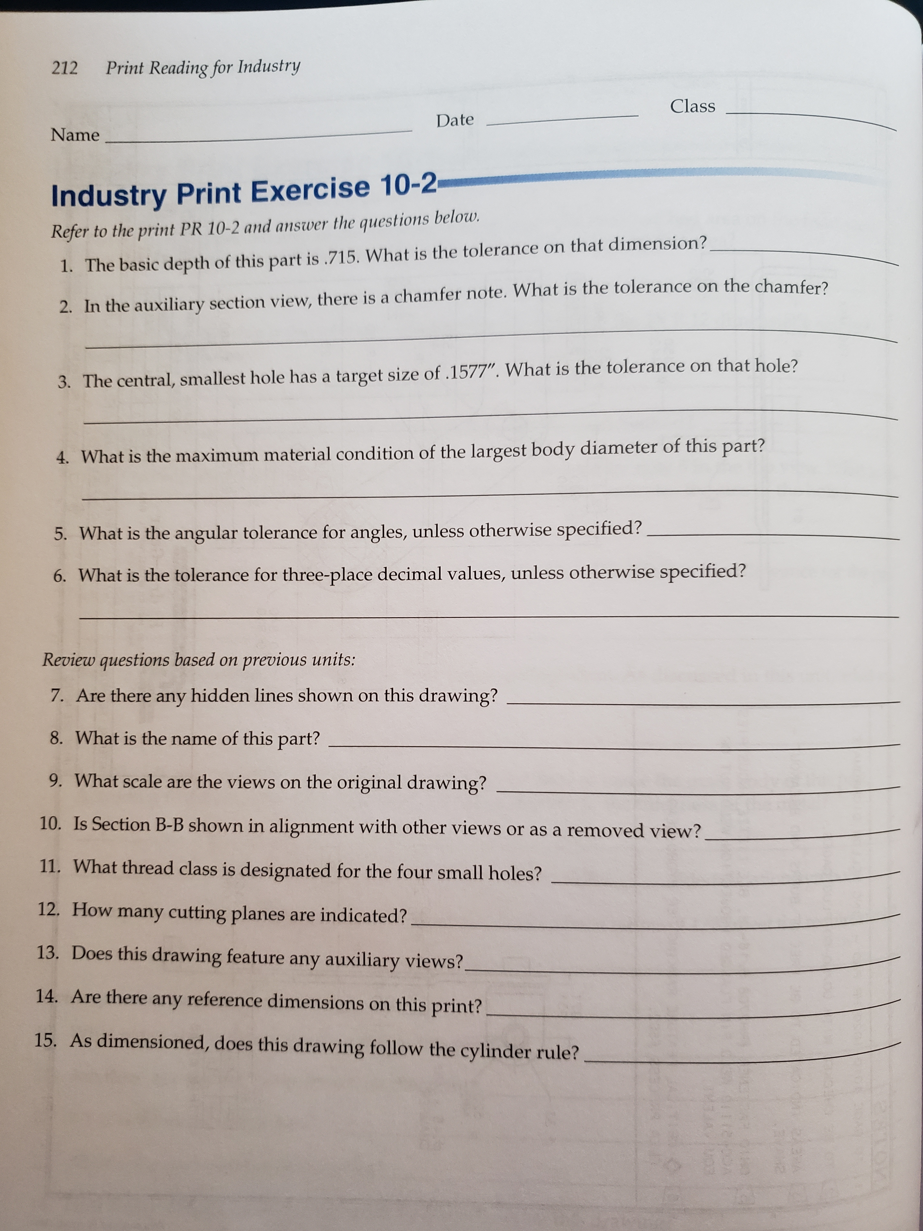
Industry Print Exercise 10-2
Refer to the print PR 10-2 and answer the questions below.
1. The basic depth of this part is .715. What is the tolerance on that dimension?
2. In the auxiliary section view, there is a chamfer note. What is the tolerance on the chamfer?
3. The central, smallest hole has a target size of .1577". What is the tolerance on that hole?
4. What is the maximum material condition of the largest body diameter of this part?
5. What is the angular tolerance for angles, unless otherwise specified?
6. What is the tolerance for three-place decimal values, unless otherwise specified?
Review questions based on previous units:
7. Are there any hidden lines shown on this drawing?
8. What is the name of this part?
9. What scale are the views on the original drawing?
10. Is Section B-B shown in alignment with other views or as a removed view?
11. What thread class is designated for the four small holes?
12. How many cutting planes are indicated?
13. Does this drawing feature any auxiliary views?.
14. Are there any reference dimensions on this print?
15. As dimensioned, does this drawing follow the cylinder rule?
OYM
94112 4
![Unless Otherwise Specifed
Tolerence
Fraction
2 Place
3 Place
Inch (Metric]
= t.015 t.38]
.010 t.25]
t.005 (t.13]
+1°
Angle
Do Not Scale Drawing
Dimenslons & Tolerance Are
In Accordance With ASME Y14.5-1994
Using The Inch System
- .715± .003
A
0.0005
118
4X HOLES MUST OPEN
INTO 4-40 TAPPED HOLES
30°-
.076
074
2X.010 CORNER BREAK-
.62
.035
- 446
030 X 45 CHAMFER
407
(R.512)
.100
R.359
ON ECC
R.464
ON ECC.
B
2X R-
.1579
D575 TARGET Ø.1577
A
0.0005/.250 A
.03X45
1.497
1.503
P1.500
0395 468
CHAMFER
431
Ø.340
ECC.
B
1.403
P1.400
D(.969)
R.03
400
544
R-
424
389
20
R.02
(445)
l.500)
B
.375
+.003
.500-001
4X 4-40 UNC-2BV 0.32 MIN. -
1.379
1.375
1.323
2X R.099 CONCENTRIC-
WITH 100 WIDE SLOT
SEE NOTE 3-
R.282
312
-.197
3X R.020 MAX.
2X R.020 MAX.
.19
A
440 417-
562-
-.47
640 TO
BOTTOM OF Ø.375
SECTION A-A
NOTES:
1. BREAK ALL SHARP CORNERS WHERE POSSIBLE
2. APPLICATIONS:
(.380)
TAP DRILL DEPTH
3. ALL POINTS LYING WITHIN THE Ø.969 MUST BE FLUSH TO 0005 BELOW
(CONCAVE) THE PLANE DEFINED BY THE AREA BETWEEN ø.969 AND Ø1.377
4X .02/.03 X 30
4. UNLESS OTHERWISE NOTED, FEATURES SHOWN ON SHALL BE
TO WITHIN+.005
CHAMFER
Part No
INLET PORTING PLATE
Part Name
SECTION B-B
Scale
2:1
Material
Check
By
Date
Drawn
By
Disk # Rev #
Rel
C
PR
ECO#
Change
No.
bo 00
C
00-9A
bodomedt
5rt
ehbege etoousolotr
Goodheart-Willcox Publish](/v2/_next/image?url=https%3A%2F%2Fcontent.bartleby.com%2Fqna-images%2Fquestion%2F15974137-7647-42c6-860e-a490543a4137%2Fc6b9ae85-ebda-441a-8705-19024610337a%2Fubanr1.jpeg&w=3840&q=75)
Transcribed Image Text:Unless Otherwise Specifed
Tolerence
Fraction
2 Place
3 Place
Inch (Metric]
= t.015 t.38]
.010 t.25]
t.005 (t.13]
+1°
Angle
Do Not Scale Drawing
Dimenslons & Tolerance Are
In Accordance With ASME Y14.5-1994
Using The Inch System
- .715± .003
A
0.0005
118
4X HOLES MUST OPEN
INTO 4-40 TAPPED HOLES
30°-
.076
074
2X.010 CORNER BREAK-
.62
.035
- 446
030 X 45 CHAMFER
407
(R.512)
.100
R.359
ON ECC
R.464
ON ECC.
B
2X R-
.1579
D575 TARGET Ø.1577
A
0.0005/.250 A
.03X45
1.497
1.503
P1.500
0395 468
CHAMFER
431
Ø.340
ECC.
B
1.403
P1.400
D(.969)
R.03
400
544
R-
424
389
20
R.02
(445)
l.500)
B
.375
+.003
.500-001
4X 4-40 UNC-2BV 0.32 MIN. -
1.379
1.375
1.323
2X R.099 CONCENTRIC-
WITH 100 WIDE SLOT
SEE NOTE 3-
R.282
312
-.197
3X R.020 MAX.
2X R.020 MAX.
.19
A
440 417-
562-
-.47
640 TO
BOTTOM OF Ø.375
SECTION A-A
NOTES:
1. BREAK ALL SHARP CORNERS WHERE POSSIBLE
2. APPLICATIONS:
(.380)
TAP DRILL DEPTH
3. ALL POINTS LYING WITHIN THE Ø.969 MUST BE FLUSH TO 0005 BELOW
(CONCAVE) THE PLANE DEFINED BY THE AREA BETWEEN ø.969 AND Ø1.377
4X .02/.03 X 30
4. UNLESS OTHERWISE NOTED, FEATURES SHOWN ON SHALL BE
TO WITHIN+.005
CHAMFER
Part No
INLET PORTING PLATE
Part Name
SECTION B-B
Scale
2:1
Material
Check
By
Date
Drawn
By
Disk # Rev #
Rel
C
PR
ECO#
Change
No.
bo 00
C
00-9A
bodomedt
5rt
ehbege etoousolotr
Goodheart-Willcox Publish
Expert Solution
This question has been solved!
Explore an expertly crafted, step-by-step solution for a thorough understanding of key concepts.

This is a popular solution!

Trending now
This is a popular solution!

Step by step
Solved in 3 steps

Knowledge Booster


Learn more about
Need a deep-dive on the concept behind this application? Look no further. Learn more about this topic, mechanical-engineering and related others by exploring similar questions and additional content below.Recommended textbooks for you
Welding: Principles and Applications (MindTap Cou…
Mechanical Engineering
ISBN:
9781305494695
Author:
Larry Jeffus
Publisher:
Cengage Learning
Welding: Principles and Applications (MindTap Cou…
Mechanical Engineering
ISBN:
9781305494695
Author:
Larry Jeffus
Publisher:
Cengage Learning