Problem 4. One of the applications of the op-amp is a comparator. Determine the output of the op-amp in each case below and justify your answer. 9V +9V +9V 2V 2V 6V Vout Vout Vout 4V 4V 4V ov -9V -9V (c) (b) (a) Vout = Vout = Vout =
Problem 4. One of the applications of the op-amp is a comparator. Determine the output of the op-amp in each case below and justify your answer. 9V +9V +9V 2V 2V 6V Vout Vout Vout 4V 4V 4V ov -9V -9V (c) (b) (a) Vout = Vout = Vout =

Delmar's Standard Textbook Of Electricity
7th Edition
ISBN:9781337900348
Author:Stephen L. Herman
Publisher:Stephen L. Herman
Chapter18: Resistive-inductive Parallel Circuits
Section: Chapter Questions
Problem 13PP: In an R-L parallel circuit, IT=1.25 amps, R=1.2k, and XL=1k. Find IR

Related questions
Question
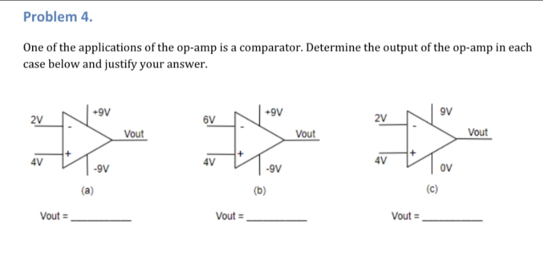
Transcribed Image Text:Problem 4.
One of the applications of the op-amp is a comparator. Determine the output of the op-amp in each
case below and justify your answer.
9V
+9V
+9V
2V
2V
6V
Vout
Vout
Vout
4V
4V
4V
ov
-9V
-9V
(c)
(b)
(a)
Vout =
Vout =
Vout =
Expert Solution
This question has been solved!
Explore an expertly crafted, step-by-step solution for a thorough understanding of key concepts.

This is a popular solution!

Trending now
This is a popular solution!

Step by step
Solved in 4 steps with 4 images

Recommended textbooks for you
Delmar's Standard Textbook Of Electricity
Electrical Engineering
ISBN:
9781337900348
Author:
Stephen L. Herman
Publisher:
Cengage Learning
Delmar's Standard Textbook Of Electricity
Electrical Engineering
ISBN:
9781337900348
Author:
Stephen L. Herman
Publisher:
Cengage Learning