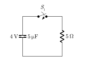
Q47 In the circuit shown below, the initial capacitor voltage is 4 V. Switch S1 is closed at t=0. The charge (in µC) lost by the capacitor form t= 25 µs to t= 100 µs is


Q: a the shown circuit, the capacitor is initially uncharged. The switch S is closed at time t=0. Find…
A: The initial voltage across capacitor is 0. When switch is closed, the circuit become series R-C…
Q: E = 245 V | R1 = 74 kΩ | R2 = 15 kΩ | R3 = 47 kΩ The capacitor in this circuit initially has no…
A: The given circuit with node markings can be drawn as:
Q: How should 4 capacitors, C1=2 µF, C2=4 µF, C3= 6 µF and C4 = 8 µF be connected to have a total…
A: Given: C1=2 μFC2=4 μFC3=6 μFC4=8 μFCeq=4.2 μF
Q: R Assume first that v, = 12V-u(-t) and X is a capacitor with C = 25mF. + (a) What is the initial…
A: Since you have asked multiple questions in a single request, we will be answering only the first…
Q: Problem 5: Suppose the switch in the following circuit is normally closed and has been closed for a…
A: First Calculate voltage across Capacitor: At t<0: When switch is closed and steady state is…
Q: R = 50 kN , = 10 V C = 0.04 µF
A:
Q: Which of the following statements is FALSE? a) The ideal capacitor completely dissipates all energy…
A: a). The ideal capacitors completly dissipates all energy supplied to it...........TRUE b).…
Q: An RC circuit has an emf of 5 V, a resistance of 10 ohms, a capacitance of 10 – 2 F, and initially a…
A: Given: An RC circuit has: EMF, Vs=5 V Resistance, R=10 ohms Capacitance, C=10-2 F The initial charge…
Q: 3. Consider an RC circuit with R = 100, C = 0.1, and Eo = 0. Suppose that the initial charge on the…
A: We need to analysis the given RC circuit .
Q: For the circuit shown Figure 3, Calculate the expression of the Ve(t) assume the initial value of…
A:
Q: Determine the current through a 100-p F capacitor if its voltage as a function of time is given by…
A:
Q: A 100-μF capacitor has a voltage given by v( t )=10−10 exp( −2t ) V. Find the power at t=0 and state…
A: Given: A capacitor whose capacitance and voltage across it is given by Formula and concept:
Q: Consider the circuit in the figure below, assuming that the value of v t = 0,-1 A flows through the…
A: Bartleby has policy to solve only first 3 subparts of a question so please reupload the question.
Q: Find the charge on the capacitor in the circuit shown in the figure, at time t=∞. C=2F R1=2Ω, R2=2Ω,…
A:
Q: (f) At what time will the capacitor reach 75.3% of its maximum charge? (In other words, t = ? when q…
A:
Q: The capacitor in the circuit shown is charged to 20 V at the time the switch is closed. If the…
A: Given data: The voltage across capacitor is: 20 V The below circuit at t > 0, The value of…
Q: L Data: C = 10 μF; L = 400 mH; R₁ = R₂ = 200 R₂ M + 200 V C At t = 0, the switch is closed. The…
A:
Q: 1. For the circuit shown below, if the maximum deflection is 0.4 and it was 0.2 for a reference…
A: The circuit diagram is: When the switch is at position “a” the capacitors are charged and when the…
Q: t=0 100 2 10 V 200 2 1 mF
A:
Q: I In the circuit below, find the value of the voltage across the capacitor assuming that the value…
A: We need to determine the current through the inductor.
Q: 8. Consider the series RC circuit below. C= 4.0mF %3D You? F1002 502 a. How should the open switch…
A: Since you have asked multiple questions in a single request, we will be answering only the first…
Q: In the shown circuit, the capacitor is initially uncharged. The switch S is closed at time t-0. Find…
A: The given circuit is series RC circuit. The charge on the capacitor is given. The voltage is given…
Q: The RC circuit shown in the figure has resistance of R=9kN and the capacitance of C=8µF. The…
A:
Q: Determine the current in the inductor, i (t), for t 0.
A:
Q: P.3. R₂ M 200 V C At t = 0, the switch is closed. The initial energy stored in the inductor and the…
A:
Q: The current through a 12 mH inductor is i(t)=30te 2t A. t> 0 s. Determine: a) The voltage across the…
A:
Q: A battery providing a constant voltage V = 10 V is connected to two resistors R = 10 Q and RL = 10 Q…
A:
Q: The voltage pulse applied to the 100mH indictor is 0 for t0. Find the inductor current as a function…
A: We know relationship between inductor current and voltage , we use that relationship to find out…
Q: The capacitor in the circuit seen has been charged to 300 V. At t=0, switch 1 closes, causing…
A: Draw the circuit at t = 0.
Q: 3. In the circuits shown the diagram below, R1 =30 N, R2 =40 Q, R3 =10 Q, and C =200 µF. R. R3 a. At…
A: In a RC circuit, time constant of the system (in both charging and discharging phase) is given by:…
Q: The switch below has been closed for a long period of time and is opened at t=0. a) Find the ENERGY…
A:
Q: 5) What is IC,max(open), the current that flows through the capacitor whose magnitude is maximum…
A:
Q: (e) An ideal 1 mF capacitor has a voltage of 10 V across its terminals for time, t 0, what is the…
A: The solution is as follows.
Q: The voltage & charge relation for a capacitor is given by V = 1+q+q². The amount of energy required…
A: Given- V=1+q+q2,q0=1C to qt=3C, To Find- Amount of energy required (E).
Q: The circuit shown below is switched at t 0. How long it takes for the capacitor to attain 70% of its…
A:
Q: The circuit shown is at steady state before the switch closes. The inductor currents are both zero…
A: Given
Q: The switch below has been closed for a long period of time and is opened at t=0. Switch_open_t=0 a)…
A: The circuit for time t<0 is drawn in the figure below. The capacitor was acting as an…
Q: Q2) Analyse the circuit given below, Obtain the equivalent capacitance of the circuit. 40 μF 10 μF…
A: The solution is as follows.
Q: The current at the terminals of the two capacitors shown is 240e-10 μA for t≥ 0. The initial values…
A: Given: Current 240e-10tμA for t≥0 Initial Value of V1 and V2 are -10V and -5V respectively.…
Q: Find the voltage across the capacitor vc for: a) t=2 s b) t = 4 s c) t= 6 s d) t= 8 s Sketch vc to…
A: Capacitor voltage equation is Vc=Vc(∞) +(Vc(initial)-Vc(∞))e-tΓVc(∞)…
Q: The voltage across a 5 mF capacitor is shown in Figure Q1(b). (1) Draw the current waveform through…
A:
Q: 4. The switch shown in Figure has been open for a long time before closing at t = 0. Write the…
A:
Q: 2.39: The switch in the circuit shown in figure beside has been closed for a long time, then 12AA…
A:
Q: The voltage across a 100-μF capacitor takes thefollowing values. Calculate the expression for…
A: Given capacitor voltage and value of capacitor is – Value of current is –
Q: A series circuit has a capacitor of 0.25 x 10-0 F, a resistor of 5x 10' 2, and an inductor of 1 H.…
A:
Q: All capacitors were initially discharged. at t = 0, S1 is placed at position 1 and S2 is closed. At…
A: 1)at t = 0, S1 is placed at position 1 and S2 is closed. At this instant Capacitors will start…
Q: The shown circuit is connected for a long time. If C=24 µF and &=5.5 V, then find the charge on the…
A:
Q: Solve i(0+) of the inductor 2H The presence of a voltage source indicates an infinite size, which…
A: In this question, We need to determine the i(0+ ) of the inductor 2H. If input voltage is Vs(t)=…
Q: a 36: The switch in the circuit shown in figure beside has been in position "a" for a long time, and…
A: In d.c. analysis, under steady state condition a capacitor will behave as OPEN CIRCUIT. The voltage…


Trending now
This is a popular solution!

Step by step
Solved in 4 steps with 1 images


- The triangular voltage pulse shown below is applied to a 200 mF capacitor. a) Write the expressions thatdescribe vc(t) in the five time intervals t < 0, 0 ≤ t ≤ 2 , 2 ≤ t ≤ 6, 6 ≤ t ≤ 8, and t > 8. b) Derive theexpressions for the capacitor current, power, and energy for the time intervals in part (a).2. A parallel plate capacitor with a plate area of 0.13 square meters separated by 1 mm is charged to 9 Volts by a battery, which is then disconnected. The plate separation is then increased to 40 mm.A. Using the expression for the capacitance of a parallel plate capacitor, what do you expect the new potential difference across the plates to be after the increase?B. Suppose you measure the potential difference across the plates after the separation and find it to be 30 V (this should be very different from what you found in part A). This unexpected result can be explained by the effects of “stray capacitance” with nearby objects. Assuming that the stray capacitance can be modeled as a capacitor connected in parallel with the parallel plate capacitor, find the value of this stray capacitance.A capacitor consists of two circular plates of radius a separated by a distance d (assume d << a). The centre of each plate is connected to the terminals of a voltage source by a thin wire. A switch in the circuit is closed at time t = 0 and a current I(t) flows in the circuit. The charge on the plate is related to the current according to I (t) = dq/dt. We begin by calculating the electric field between the plates. Throughout this problem you may ignore edge effects. We assume that the electric field is zero for r > a. (A) Use Gauss’ Law to find the electric field between the plates as a function of time t, in terms of q(t), a, ε, and π. The vertical direction is the k (b) Now take an imaginary flat disc of radius r < a inside the capacitor, as shown below. Using your expression for E above, calculate the electric flux through this flat disc of radius r < a in the plane midway between the plates, in terms of r, q(t), a, and ε. (C) Calculate the Maxwell…
- IN THE CIRCUIT SHOWN, CONSIDER THAT V1=20 VDC, R1=1000 Ω, R2=3000 Ω, R3=3500 Ω AND C=1 mF.DETERMINE:A) THE TIME IT TAKES FOR THE CAPACITOR TO REACH ITS FINAL VALUE (5T), WHEN SWITCH 2 (INT 2) IS IN POSITION A AND SWITCH 1 (INT 1) IS CLOSED AT t=0,B) THE ENERGY STORED BY THE CAPACITOR ONCE IT HAS BEEN FULLY CHARGED WITH THE SAME POSITION OF SWITCHES AS ITEM A)C) ONCE THE CAPACITOR HAS BEEN FULLY CHARGED WITH SWITCH 1 CLOSED, SWITCH 2 MOVES POSITION (GOES TO B) AT A NEW t=0. NOW DETERMINE THE VALUE OF THE VOLTAGE ON THE CAPACITOR AT t=3.5 SECONDSDerive an expression for the electrical energy stored in a capacitor of capacitance C when charged to a potential difference V. If C = 2µF and V= 4V, calculate(l.) the final energy stored in the capacitor,(II.) the work done by the battery in the charging process Account for any difference between your answers in parts (I) and (II) above. If a 4μF capacitor is connected to a constant current source, therefore its current is given in the equation ic(t)=10mA. Determine the voltage, power and energy at 2ms.
- Can you please help with this question? The triangular voltage pulse shown below is applied to a 200 mF capacitor. a) Write the expressions thatdescribe vc(t) in the five time intervals t < 0, 0 ≤ t ≤ 2 , 2 ≤ t ≤ 6, 6 ≤ t ≤ 8, and t > 8. b) Derive theexpressions for the capacitor current, power, and energy for the time intervals in part (a).Prior to t=0, the current in a 2-H inductance is zero. Starting at t=0, the current is increased linearly with time to 10 A in 5 s. Then, the current remains constant at 10 A. Sketch the voltage, current, power, and stored energy to scale versus time.Consider a coaxial capacitor, radius a and b, and length L, as shown in the figure below.The capacitor it is partially filled with dielectric (ɛ, length D).The rest is air (ɛ0). Consider that (L, D >> (b-a)). The inner conductor (r = a) is held at constant potential V and the outer conductor (r = b) is grounded.I)Determine capacitanceIl)Consider the situations D → 0 and D → L. Determine the new capacitance values
- A capacitor consists of two circular plates of radius a separated by a distance d(assume d << a). The centre of each plate is connected to the terminals of a voltagesource by a thin wire. A switch in the circuit is closed at time t = 0 and a current I(t) flows in the circuit. Thecharge on the plate is related to the current according to I (t) = dq/dt. We begin bycalculating the electric field between the plates. Throughout this problem you mayignore edge effects. We assume that the electric field is zero for r > a.(A) Use Gauss’ Law to find the electric field between the plates as a functionof time t, in terms of q(t), a, ε, and π. The vertical direction is the k direction. (B)Now take an imaginary flat disc of radius r < a inside the capacitor, as shownbelow. Using your expression for E above, calculate the electric flux through this flatdisc of radius r < a in the plane midway between the plates, in terms of r, q(t), a,and ε. (C)Calculate the Maxwell displacement…Given an initially charged capacitance that begins to discharge through a resistance at t=0, what percentage of the initial voltage remains at two time constants? What percentage of the initial stored energy remains?The voltage across an inductance L is given by v( t )= V m cos( ωt ). The current is zero at t=0 .Suppose that is very large ideally, approaching infinity. For this voltage, does the inductance approximate either an open or a short circuit? Explain.