Question 4 A beam made up of two unequal leg angles is subjected bending moment M having to a its vector at an angle 0 to the z axis as shown in Figure Q4 For the position shown, determine the onentation of the neutral axis 4.1 Calculate the maximum tensile stress and maximum compressive stress in the beam 4.2 Assume that 0 3.5 kNm 30° and M = 120 mmx80 mmx12 mm 120 mm 12 mm 80 mm Figure Q4
Question 4 A beam made up of two unequal leg angles is subjected bending moment M having to a its vector at an angle 0 to the z axis as shown in Figure Q4 For the position shown, determine the onentation of the neutral axis 4.1 Calculate the maximum tensile stress and maximum compressive stress in the beam 4.2 Assume that 0 3.5 kNm 30° and M = 120 mmx80 mmx12 mm 120 mm 12 mm 80 mm Figure Q4

Mechanics of Materials (MindTap Course List)
9th Edition
ISBN:9781337093347
Author:Barry J. Goodno, James M. Gere
Publisher:Barry J. Goodno, James M. Gere
Chapter6: Stresses In Beams (advanced Topics)
Section: Chapter Questions
Problem 6.5.8P: The cross section of a steel beam is shown in the figure. This beam is subjected to a bending moment...

Related questions
Question
Transcribed Image Text:Question 4
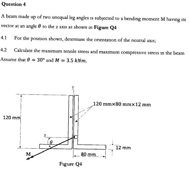
A beam made up of two unequal leg angles is subjected
bending moment M having
to a
its
vector at an angle 0 to the z axis as shown in Figure Q4
For the position shown, determine the onentation of the neutral axis
4.1
Calculate the maximum tensile stress and maximum compressive stress in the beam
4.2
Assume that 0
3.5 kNm
30° and M
=
120 mmx80 mmx12 mm
120 mm
12 mm
80 mm
Figure Q4
Expert Solution
This question has been solved!
Explore an expertly crafted, step-by-step solution for a thorough understanding of key concepts.

This is a popular solution!

Trending now
This is a popular solution!

Step by step
Solved in 5 steps with 5 images

Recommended textbooks for you
Mechanics of Materials (MindTap Course List)
Mechanical Engineering
ISBN:
9781337093347
Author:
Barry J. Goodno, James M. Gere
Publisher:
Cengage Learning
Mechanics of Materials (MindTap Course List)
Mechanical Engineering
ISBN:
9781337093347
Author:
Barry J. Goodno, James M. Gere
Publisher:
Cengage Learning