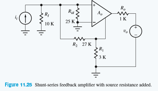
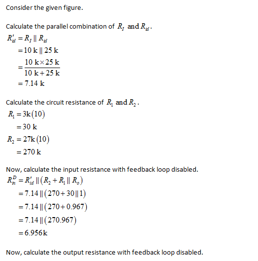
R. R Rid A. (1) 25 K 10 K R, 27 K R1 ЗК Figure 11.25 Shunt-series feedback amplifier with source resistance added.


Q: Consider the ideal shunt-series feedback amplifier in Figure below. Assume that the source…
A:
Q: A dynamometer consists of an inner loop having a differentiator feedback, and a main loop which has…
A: Question has multiple parts. Since you have not mentioned which part you are looking for, so we are…
Q: An ideal series-shunt feedback amplifier is shown in Figure 12.6. Assume RS is negligibly small, (a)…
A: Given: Vi=100mVVfb=99mVV0=5VRi=kΩR0=kΩ to find: AvβvAvfRifRof
Q: A negative-feedback amplifier has a closed-loop gain of 200 V/V and an open-loop gain of 104 V/V.…
A:
Q: 5. A realistic amplifier can be modeled by the following non-linear transfer function. For this…
A: Given data, The open-loop gain changes from 1000 to 100.
Q: Consider the series-shunt feedback amplifier of Figure below. Assume that the voltage divider (R1,…
A: Given : Series Shunt Feedback Amplifier Voltage divider R1,R2 is implemented with 1M ohm…
Q: 3: Prove that: 1:- Ac-Current gain of collector feedback amplifier is a proximally Ry/Rc.
A: Since you have asked multiple questions in a single request, we will be answering only the 1st…
Q: An amplifier has an open-loop gain of 92 dB, Rid = 75 kΩ, and Ro = 1400Ω. The amplifier is used in a…
A: a) Calculating absolute open loop gain
Q: Find the loop gain, ideal current gain, actual current gain, input resistance, and output resistance…
A: Calculating ideal current gain
Q: Feedback: 2. An ideal series-shunt feedback amplifier has Rs negligibly small. If Vi = 100mV, Vfb…
A: Series-shunt feedback system: This system works as the true voltage amplifier because the input…
Q: Find the loop gain, current gain, input resistance, and output resistance for the shunt-series…
A:
Q: (b) For a series shunt feedback system, the open loop gain Av and closed-loop gain Arof the…
A: To analyse the given statement
Q: A negative-feedback amplifier has a closed-loop gain of 200 V/V and an open-loop gain of 104 V/V.…
A:
Q: The transistor parameters for the circuit shown are VTN = 0.4 V, Kn = 0.5 mA/V2, and λ = 0. (a)…
A:
Q: Q.2 (a) The open-loop gain of an amplifier is A = 60 dB. If the open-loop gain decreases by 30 pero…
A: a) We know the relation between open loop and closed loop gain as Af=A1+βAdAfAf=11+βA*dAA Given…
Q: for identical transistors Hfe=100 and hie=2,5K. according to the elements and values given on the…
A: It is given the identical transistors hfe=100 , hie=2.5 kΩ We need to determine the feedback…
Q: Feedback: 3. An ideal shunt-shunt feedback amplifier has Rs =∞ . If Ii = 100 microAmp, I fb = 99…
A:
Q: Frequency, and feedback analysis 2. An amplifier with a midband gain AM=1000 and a dominant pole…
A: Answer: For the closed loop amplifier, the mid-band gain AMf is calculated by using the following…
Q: If the gain (Av) of the inverting amplifier is 3 and Rin=1.6 kQ, the value of the feedback resistor…
A: To answer above question, one should know what an amplifier is. An amplifier is an electronic…
Q: For the amplifier circuit shown, determine the current gain Ai = lo/Ils using ideal feedback…
A: Given data is- hfe1=hfe2=100hie1=30 kΩhie2=1.5 kΩRL=1 kΩRC=0.1 kΩ Calculating Current gain A=I∘Is
Q: Find the loop gain, ideal voltage gain, actual voltage gain, input resistance, and output resistance…
A:
Q: Q-4: For the collector-feedback circuit shown in Figure 3, determine the percent change in the…
A:
Q: An amplifier has open loop gain of 110 and output resistance is 50(kohm). If amplifier is feedback…
A: Given values are - Open loop gainA=110Output resistanceROL=50kohm=50000ohmFeedback factorβ=0.2 Given…
Q: Consider the series-shunt feedback amplifier of Figure below. Assume that the voltag divider (R1,…
A: The given circuit diagram is shown below: It is given that: gm=4 mA/VRD=10 KΩClosed loop…
Q: Q2/ For a unity feedback'system the open loop transfer function is given by: GSHIS) K S(s • 28 + 7))…
A:
Q: Consider a voltage series feedback network, where amplifier gain = 100, feedback factor = 5. For the…
A:
Q: Q-4: A- What are the effects of negative voltage-series feedback on the characteristics of an…
A:
Q: Which of these amplifier configuration has a large input impedance, low output impedance and an…
A: (i) The terminal that is connected to the base i.e. base terminal of transistor would be shared…
Q: Assume an operational amplifier is working on inverting amplifer in which it takes input resistance…
A: The solution can be achieved as follows.
Q: 4. The circuit uses current- (or shunt-) feedback bias. The Si transistor has ICEO = 0, VCEsat =0,…
A: For the current feedback bias circuit,ICE = 0VCE(sat)=0β=100RC=2kΩVCC=12V
Q: A negative-feedback amplifier has a closed-loop gain of 200 V/V and an open-loop gain of 104 V/V.…
A:
Q: The gain of an amplifier without feedback is 2000. When negative feedback is applied, gain becomes…
A: The gain of an amplifier with negative feedback can be expressed as Af=A1+Aβ--->(1) where A is…
Q: A unity feedback system has the open loop transfer function shown below. Find the gain at the…
A: The open-loop transfer is shown below: HG(s)=Ks(s+3)(s2+2s+2) The unity feedback closed-loop…
Q: A unity feedback system has a forward path transfer function K Gs) = s(s+ 8) %3D where K is the gain…
A: Given Gs=Kss+8Hs =1 Closed loop transfer function =Gs1+GsHs…
Q: The classic feedback amplifier as shown has β =0.125. What are the loop gain T, ideal closedloop gain…
A: a) Given β=0.125A=∞ Calculating transmission gain T T=AβT=∞0.125T=∞
Q: Assume an operational amplifier is working on inverting amplifier in which it takes input resistance…
A: An operational amplifier is a high-gain amplifier incorporating feedback for controlling its…
Q: Consider an amplifier with the loop gain function T(f), where ßis the feedback gain and frp is the…
A: Given: Consider an amplifier with the loop gain function T(f): Tf=β1041+jffPD1+jf105 where β is the…
Q: Q1): Sketch the polar plot for the unity feedback system shown below and compute the gain margin and…
A: We will first plot the Nyquist plot of the given transfer function. As we know the polar plot is a…
Q: Q1 (A): Sketch the Nyquist plot of the unity feedback system that shown in figure (1). Is the close…
A:
Q: Assume an operational amplifier is working on inverting amplifier in which it takes input resistance…
A: When the input of Op-amp is change from inverting terminal to non-inverting terminal, then the…
Q: Consider the open loop transfer function, below, which is placed in a unity gain feedback…
A:
Q: Consider the series-shunt feedback amplifier of Figure below. Assume that the voltage divider (R1,…
A:
Q: Q1: Drow and determine the center frequency, maximum gain, and bandwidth for the multiple-feedback…
A: Given,For the multiple-feedback band pass circuit,The values of the resistances…
Q: Consider the series-shunt feedback amplifier of Figure below. Assume that the voltage divider (R1,…
A:
Q: Q1 (A): Sketch the Nyquist plot of the unity feedback system that shown in figure (1). Is the close…
A:
Q: The open-loop gain of an amplifier is A 350. and the feedback factor is 8 = 0.7. (a) Determine the…
A: a) Af=S0Si =A1+Aβ = 3501+350×0.7 =3501+245 =1.4226
Q: Find the value of output voltage and closed loop gain of non-inverting amplifier if input voltage is…
A: Given: Input voltage = 50mV Input resistance = Ri=50 kΩ Feed back resistance = Rf=1 MΩ
Find the loop gain, closed-loop current gain, input resistance, and output resistance for the shunt-series feedback amplifier as shown, if R1 and R2 are increased in value by a factor of 10.

Step by step
Solved in 2 steps with 3 images


- 2. Design a unity gain inverting summing amplifier that will output the sum of two input voltages. Use a feedback resistor of 2.5 Kohms.For the feedback amplifier circuit shown below, assuming the internal resistor in each MOSFETs is infinite ( ro = ∞ ) and gm1 = gm2 = gm2 = 2.5mA/V. a) Draw the small AC equivalent circuit of the below amplifier. b) Determine the overall voltage gain.for identical transistors Hfe=100 and hie=2,5K. according to the elements and values given on the circuit; Determine the feedback topology of the circuit. Draw the non-feedback locator circuit taking into account the feedback effect. Assuming |βA|>>1 , find the feedback gain and voltage gain of the circuit.
- Find the value of output voltage and closed loop gain of non-inverting amplifier if input voltage is 50 milivolt and it has input resistance of 50 kohm and feedback resistance of 1 Mohm. NOTE : KINDLY ELABORATE BRIEFLYAssume an operational amplifier is working on inverting amplifer in which it takes input resistance and feedback resistance of 30 ohm and 60 ohm respectively. If input voltage is applied at 150 volt then examine following parameters 1.If input voltage is changed from inverting terminal to non inverting terminal then calculate its output voltage 2. If we add one more input resistance of 40 ohm at inverting terminal at 20 voit input supply voltage and working as adder then calculate the output voltage.An amplifier has an open-loop voltage gain of 90 dB, Rid = 50 kΩ, and Ro = 5000 Ω. The amplifier is used in a feedback configuration with a resistive feedback network. (a) What is the largest current gain that can be achieved with this feedback amplifier? (b) What is the largest transconductance that can be achieved with this feedback amplifier?
- An amplifier has an open-loop gain of 92 dB, Rid = 75 kΩ, and Ro = 1400Ω. The amplifier is used in a feedback amplifier configuration with a resistive feedback network. (a) What is the largest value of current gain that can be achieved with this feedback amplifier? (b) What is the largest valuetransconductance that can be achieved with this feedback amplifier?For the cascaded amplifier of the figure below, calculate the input impedance of the first stage, output impedance of the second stage, total voltage gain, and the output voltage if Vs= 1mV.Find the loop gain, ideal current gain, actual current gain, input resistance, and output resistance for the feedback amplifier shown with RI = 150 kΩ, RL = 5k Ω, R1 = 10 kΩ and R 2 =1kΩ.
- Find the loop gain, ideal transresistance, actual transresistance, input resistance, and output resistance for the feedback amplifier shown with RI =100kΩ, RL =15kΩ, and RF =10kΩ.What is the gain AV = Vout/Vin of the amplifier? Av= ?Assume an operational amplifier is working on inverting amplifier in which it takes input resistance and feedback resistance of 30ohm and 60ohm respectively.If input voltage is applied at 150 volt then examine following parameters. If input voltage is changed from inverting terminal to non inverting terminal then calculate its output voltage. Options: A)400 volt B)450 volt C)500 volt D)550 volt