Read the QNET On-Off and PID Control (DC Motor Speed Control) background material in the PDF document on Moodle The speed of the DC motor is controlled using a proportional-integral control system. The block diagram of the closed-loop system is shown below. к y=e Ts+1 DC Motor PI speed control closed-loop block diagram 2(s) К G(s) The transfer function representing the DC motor speed-voltage relation The input-output relation in the time-domain for a PI controller with set-point weighting is: is used to design the PI controller k,(r-y) u-k, (br-y)+ sp where k, is the proportional gain, ki is the integral gain, and bn is the set-point weight (refer to background reading) Note: There is no tachometer sensor present on the QNET DC motor system that measures the speed. Instead the amplifier board has circuitry that computes the derivative of the encoder signal, i.e. a digital tachometer. However to minimize the noise of the measured signal and increase the overall robustness of the system, the following first-order low-pass filter is used: m,meas T,s+ Parameter Tyis the filter time constant that determines the cutoff frequency and mmeas is the measured speed signal
Read the QNET On-Off and PID Control (DC Motor Speed Control) background material in the PDF document on Moodle The speed of the DC motor is controlled using a proportional-integral control system. The block diagram of the closed-loop system is shown below. к y=e Ts+1 DC Motor PI speed control closed-loop block diagram 2(s) К G(s) The transfer function representing the DC motor speed-voltage relation The input-output relation in the time-domain for a PI controller with set-point weighting is: is used to design the PI controller k,(r-y) u-k, (br-y)+ sp where k, is the proportional gain, ki is the integral gain, and bn is the set-point weight (refer to background reading) Note: There is no tachometer sensor present on the QNET DC motor system that measures the speed. Instead the amplifier board has circuitry that computes the derivative of the encoder signal, i.e. a digital tachometer. However to minimize the noise of the measured signal and increase the overall robustness of the system, the following first-order low-pass filter is used: m,meas T,s+ Parameter Tyis the filter time constant that determines the cutoff frequency and mmeas is the measured speed signal

Power System Analysis and Design (MindTap Course List)
6th Edition
ISBN:9781305632134
Author:J. Duncan Glover, Thomas Overbye, Mulukutla S. Sarma
Publisher:J. Duncan Glover, Thomas Overbye, Mulukutla S. Sarma
Chapter12: Power System Controls
Section: Chapter Questions
Problem 12.2P

Related questions
Question
The background readgin ( if you needed) is on the screenshot
- Determine the closed loop transfer function from the speed reference, r, to the angular motor speed output, ω, i.e., Y(s)/R(s).
- Determine kp and ki in terms of the closed-loop natural frequency, ωn, damping ratio, ζ, motor time constant, τ, and motor gain constant, K.
- Based on your results from (1) and (2), how would large values of the controller gains, kp and ki, affect the closed-loop undamped natural frequency of the system?
- Explain how bsp can be used to adjust the speed and overshoot of the response to reference values. (Hint: When answering this question, explain how the value of bsp affects the locations of the closed-loop zeros and/or poles.)
Transcribed Image Text:Read the QNET On-Off and PID Control (DC Motor Speed Control) background material in the PDF document on Moodle
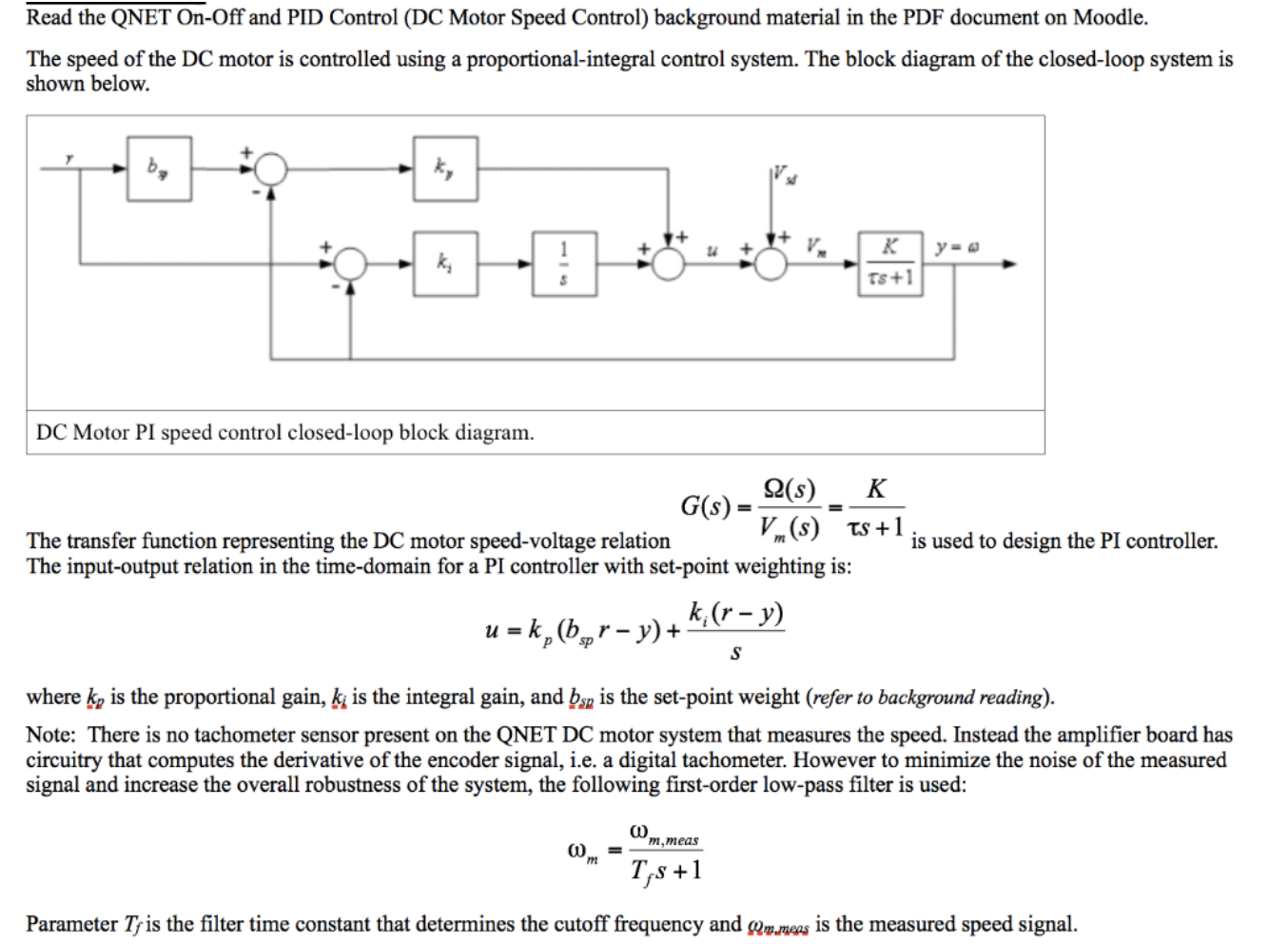
The speed of the DC motor is controlled using a proportional-integral control system. The block diagram of the closed-loop system is
shown below.
к
y=e
Ts+1
DC Motor PI speed control closed-loop block diagram
2(s)
К
G(s)
The transfer function representing the DC motor speed-voltage relation
The input-output relation in the time-domain for a PI controller with set-point weighting is:
is used to design the PI controller
k,(r-y)
u-k, (br-y)+
sp
where k, is the proportional gain, ki is the integral gain, and bn is the set-point weight (refer to background reading)
Note: There is no tachometer sensor present on the QNET DC motor system that measures the speed. Instead the amplifier board has
circuitry that computes the derivative of the encoder signal, i.e. a digital tachometer. However to minimize the noise of the measured
signal and increase the overall robustness of the system, the following first-order low-pass filter is used:
m,meas
T,s+
Parameter Tyis the filter time constant that determines the cutoff frequency and mmeas is the measured speed signal
Expert Solution
This question has been solved!
Explore an expertly crafted, step-by-step solution for a thorough understanding of key concepts.

This is a popular solution!

Trending now
This is a popular solution!

Step by step
Solved in 8 steps with 7 images

Knowledge Booster


Learn more about
Need a deep-dive on the concept behind this application? Look no further. Learn more about this topic, electrical-engineering and related others by exploring similar questions and additional content below.Recommended textbooks for you
Power System Analysis and Design (MindTap Course …
Electrical Engineering
ISBN:
9781305632134
Author:
J. Duncan Glover, Thomas Overbye, Mulukutla S. Sarma
Publisher:
Cengage Learning
Power System Analysis and Design (MindTap Course …
Electrical Engineering
ISBN:
9781305632134
Author:
J. Duncan Glover, Thomas Overbye, Mulukutla S. Sarma
Publisher:
Cengage Learning