Refer to the figure which shows a ship's propeller, drive train, engine, and flywheel. The diameter ratio of the gears is D1/D2=2/3. The inertias in kg-m2 of gear 1 and gear 2 are 100 and 500, respectively. The flywheel, engine, and propeller inertias are 104, 103, and 2500, respectively. The torsional stiffness of shaft 1 is 5x10⁶ N-m/rad, and that of shaft 2 is 106 N-m/rad. Because the flywheel inertia is so much larger than the other inertias, a simpler model of the shaft vibrations can be obtained by assuming the flywheel does not rotate. In addition, because the shafts between the engine, gears and propeller are short, we will assume that they are very stiff compared to shaft 2. However, there are losses in the gear system which are represened by a damper with a damping coefficient of 300 Ns/rad. If we also disregard the shaft inertias, the resulting model consists of two inertias, one obtained by lumping the engine and gear inertias, and one for the propeller as seen in the figure below. kr2 ll a. Using these assumptions, what are the degrees of freedom of the system and what order do you expect the characteristic equation to be? b. Develop the system of dynamic equations for this engine / propeller. c. Find the characteristic equation using the Laplace transform method.
Refer to the figure which shows a ship's propeller, drive train, engine, and flywheel. The diameter ratio of the gears is D1/D2=2/3. The inertias in kg-m2 of gear 1 and gear 2 are 100 and 500, respectively. The flywheel, engine, and propeller inertias are 104, 103, and 2500, respectively. The torsional stiffness of shaft 1 is 5x10⁶ N-m/rad, and that of shaft 2 is 106 N-m/rad. Because the flywheel inertia is so much larger than the other inertias, a simpler model of the shaft vibrations can be obtained by assuming the flywheel does not rotate. In addition, because the shafts between the engine, gears and propeller are short, we will assume that they are very stiff compared to shaft 2. However, there are losses in the gear system which are represened by a damper with a damping coefficient of 300 Ns/rad. If we also disregard the shaft inertias, the resulting model consists of two inertias, one obtained by lumping the engine and gear inertias, and one for the propeller as seen in the figure below. kr2 ll a. Using these assumptions, what are the degrees of freedom of the system and what order do you expect the characteristic equation to be? b. Develop the system of dynamic equations for this engine / propeller. c. Find the characteristic equation using the Laplace transform method.

Elements Of Electromagnetics
7th Edition
ISBN:9780190698614
Author:Sadiku, Matthew N. O.
Publisher:Sadiku, Matthew N. O.
ChapterMA: Math Assessment
Section: Chapter Questions
Problem 1.1MA

Related questions

Question
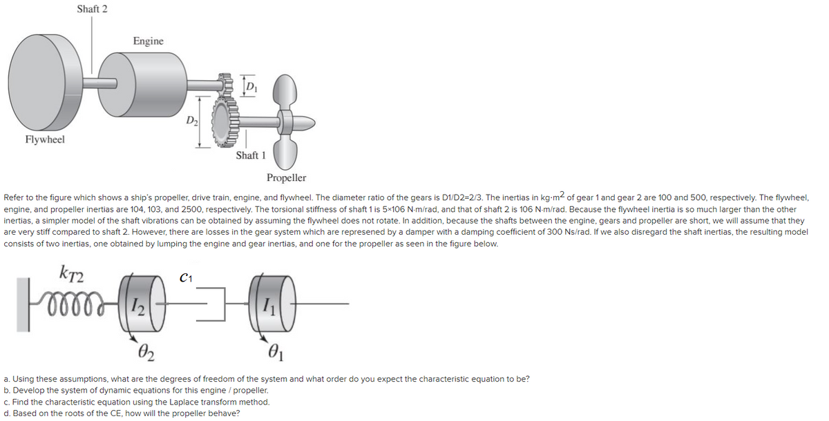
Transcribed Image Text:Shaft 2
Engine
D2
Flywheel
Shaft 1
Propeller
Refer to the figure which shows a ship's propeller, drive train, engine, and flywheel. The diameter ratio of the gears is D1/D2=2/3. The inertias in kg-m2 of gear 1 and gear 2 are 100 and 500, respectively. The flywheel,
engine, and propeller inertias are 104, 103, and 2500, respectively. The torsional stiffness of shaft 1 is 5×10⁶ N-m/rad, and that of shaft 2 is 106 N-m/rad. Because the flywheel inertia is so much larger than the other
inertias, a simpler model of the shaft vibrations can be obtained by assuming the flywheel does not rotate. In addition, because the shafts between the engine, gears and propeller are short, we will assume that they
are very stiff compared to shaft 2. However, there are losses in the gear system which are represened by a damper with a damping coefficient of 300 Ns/rad. If we also disregard the shaft inertias, the resulting model
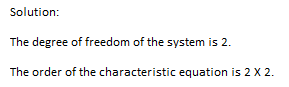
consists of two inertias, one obtained by lumping the engine and gear inertias, and one for the propeller as seen in the figure below.
kr2
C1
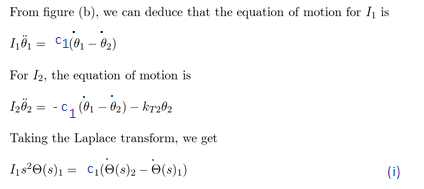
a. Using these assumptions, what are the degrees of freedom of the system and what order do you expect the characteristic equation to be?
b. Develop the system of dynamic equations for this engine / propeller.
c. Find the characteristic equation using the Laplace transform method.
d. Based on the roots of the CE, how will the propeller behave?
Expert Solution
Step 1

Trending now
This is a popular solution!

Step by step
Solved in 2 steps with 3 images

Knowledge Booster


Learn more about
Need a deep-dive on the concept behind this application? Look no further. Learn more about this topic, mechanical-engineering and related others by exploring similar questions and additional content below.Recommended textbooks for you
Elements Of Electromagnetics
Mechanical Engineering
ISBN:
9780190698614
Author:
Sadiku, Matthew N. O.
Publisher:
Oxford University Press

Mechanics of Materials (10th Edition)
Mechanical Engineering
ISBN:
9780134319650
Author:
Russell C. Hibbeler
Publisher:
PEARSON

Thermodynamics: An Engineering Approach
Mechanical Engineering
ISBN:
9781259822674
Author:
Yunus A. Cengel Dr., Michael A. Boles
Publisher:
McGraw-Hill Education
Elements Of Electromagnetics
Mechanical Engineering
ISBN:
9780190698614
Author:
Sadiku, Matthew N. O.
Publisher:
Oxford University Press
Mechanics of Materials (10th Edition)
Mechanical Engineering
ISBN:
9780134319650
Author:
Russell C. Hibbeler
Publisher:
PEARSON
Thermodynamics: An Engineering Approach
Mechanical Engineering
ISBN:
9781259822674
Author:
Yunus A. Cengel Dr., Michael A. Boles
Publisher:
McGraw-Hill Education

Control Systems Engineering
Mechanical Engineering
ISBN:
9781118170519
Author:
Norman S. Nise
Publisher:
WILEY

Mechanics of Materials (MindTap Course List)
Mechanical Engineering
ISBN:
9781337093347
Author:
Barry J. Goodno, James M. Gere
Publisher:
Cengage Learning

Engineering Mechanics: Statics
Mechanical Engineering
ISBN:
9781118807330
Author:
James L. Meriam, L. G. Kraige, J. N. Bolton
Publisher:
WILEY