shows the block diagram of an electric locomotive motor where wa is the desire motor as set by the driver whilst w is the actual angular velocity achieved. The bl he load transfer function (i.e. the locomotive) whilst G¡(s) is the armature controle The locomotive motor can experience torque disturbances due to braking, given w(s) ransfer functions relating output angular velocity to desired angular velocity, wa(s) ocity to torque disturbance, , given w(s) T«(s) * 10 G|(s) = s+ 1 1 G2(s) = 2s + 0.5 Ta(s) 540 G|(s) G2(s) 0.1 Figure O3
shows the block diagram of an electric locomotive motor where wa is the desire motor as set by the driver whilst w is the actual angular velocity achieved. The bl he load transfer function (i.e. the locomotive) whilst G¡(s) is the armature controle The locomotive motor can experience torque disturbances due to braking, given w(s) ransfer functions relating output angular velocity to desired angular velocity, wa(s) ocity to torque disturbance, , given w(s) T«(s) * 10 G|(s) = s+ 1 1 G2(s) = 2s + 0.5 Ta(s) 540 G|(s) G2(s) 0.1 Figure O3

Power System Analysis and Design (MindTap Course List)
6th Edition
ISBN:9781305632134
Author:J. Duncan Glover, Thomas Overbye, Mulukutla S. Sarma
Publisher:J. Duncan Glover, Thomas Overbye, Mulukutla S. Sarma
Chapter11: Transient Stability
Section: Chapter Questions
Problem 11.18P

Related questions
Question
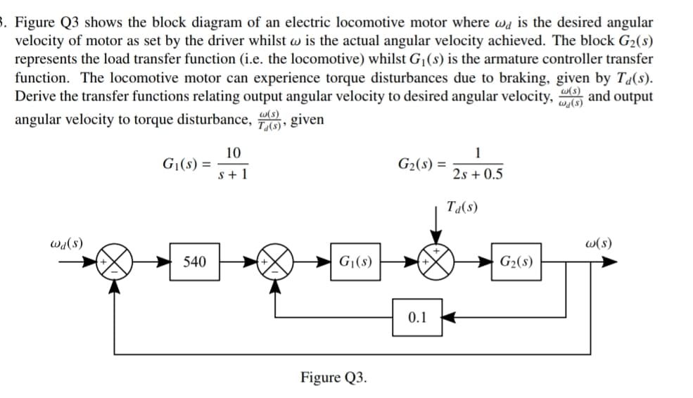
Transcribed Image Text:8. Figure Q3 shows the block diagram of an electric locomotive motor where wa is the desired angular
velocity of motor as set by the driver whilst w is the actual angular velocity achieved. The block G2(s)
represents the load transfer function (i.e. the locomotive) whilst G¡(s) is the armature controller transfer
function. The locomotive motor can experience torque disturbances due to braking, given by T4(s).
Derive the transfer functions relating output angular velocity to desired angular velocity, and output
w(s)
wa(s)
w(s)
angular velocity to torque disturbance, , given
10
G|(s) =
s+ 1
1
G2(s) =
2s + 0.5
Ta(s)
w(s)
(s)PM
G|(s)
540
G2(s)
0.1
Figure Q3.
Expert Solution
This question has been solved!
Explore an expertly crafted, step-by-step solution for a thorough understanding of key concepts.

Step by step
Solved in 4 steps with 4 images

Knowledge Booster


Learn more about
Need a deep-dive on the concept behind this application? Look no further. Learn more about this topic, electrical-engineering and related others by exploring similar questions and additional content below.Recommended textbooks for you
Power System Analysis and Design (MindTap Course …
Electrical Engineering
ISBN:
9781305632134
Author:
J. Duncan Glover, Thomas Overbye, Mulukutla S. Sarma
Publisher:
Cengage Learning
Power System Analysis and Design (MindTap Course …
Electrical Engineering
ISBN:
9781305632134
Author:
J. Duncan Glover, Thomas Overbye, Mulukutla S. Sarma
Publisher:
Cengage Learning