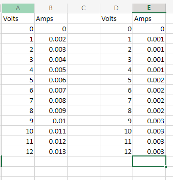
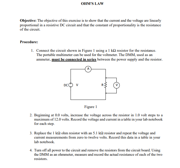
So this question is how to complete these instructions given the lab procedure put in the first picture below. The second picture is all the recorded data. The A and B columns are the 1K ohms resistor and the C and D columns are the 5.1K ohms resistors. I am having a hard time being able to get a graph set up the way they would like it I hope someone can help thank you. 1.Use your data to create graphs of current versus voltage for the two resistors. Note that voltage is the independent variable and it must be plotted on the horizontal axis. Use linear scales and label them properly. 2. Draw the single "best" straight line through the data points for each resistor. DO NOT "CONNECT THE DOTS!" Your straight lines may not necessarily touch all, or even any, of the plotted data points. Make sure that all scales are properly labeled and that each line is labeled according to the nominal resistor value that was used for that data set. 3. Choose two convenient points on each of your straight lines and use them to calculate the slopes of your lines. It is better if you do not choose two points that are very close together. These slopes represent the reciprocal resistance, or conductance, values for each of your two circuits. 4. Calculate the reciprocals of each of the slopes determined in step 3, above. Create a table that compares these resistance values with the nominal and measured resistance values.


Protection System
A system that protects electrical systems from faults by isolating the problematic part from the remainder of the system, preventing power from being cut from healthy elements, improving system dependability and efficiency is the protection system. Protection devices are the equipment that are utilized to implement the protection system.
Predictive Maintenance System
Predictive maintenance technologies are designed to assist in determining the state of in-service equipment so that maintenance can be scheduled. Predictive maintenance is the application of information; proactive maintenance approaches examine the condition of equipment and anticipate when it should maintain. The purpose of predictive maintenance is to forecast when equipment will fail (depending on a variety of parameters), then prevent the failure through routine and corrective maintenance.Condition monitoring is the continual monitoring of machines during process conditions to maintain optimal machine use, which is necessary for predictive maintenance. There are three types of condition monitoring: online, periodic, and remote. Finally, remote condition monitoring allows the equipment observed from a small place and data supplied for analysis.
Preventive Maintenance System
To maintain the equipment and materials on a regular basis in order to maintain those running conditions and reduce unnecessary shutdowns due to unexpected equipment failure is called Preventive Maintenance (PM).
So this question is how to complete these instructions given the lab procedure put in the first picture below. The second picture is all the recorded data. The A and B columns are the 1K ohms resistor and the C and D columns are the 5.1K ohms resistors. I am having a hard time being able to get a graph set up the way they would like it I hope someone can help thank you.
1.Use your data to create graphs of current versus voltage for the two resistors. Note that
voltage is the independent variable and it must be plotted on the horizontal axis. Use
linear scales and label them properly.
2. Draw the single "best" straight line through the data points for each resistor. DO NOT
"CONNECT THE DOTS!" Your straight lines may not necessarily touch all, or even
any, of the plotted data points. Make sure that all scales are properly labeled and that
each line is labeled according to the nominal resistor value that was used for that data
set.
3. Choose two convenient points on each of your straight lines and use them to calculate the
slopes of your lines. It is better if you do not choose two points that are very close together.
These slopes represent the reciprocal resistance, or conductance, values for each of your
two circuits.
4. Calculate the reciprocals of each of the slopes determined in step 3, above. Create a table
that compares these resistance values with the nominal and measured resistance values.


Trending now
This is a popular solution!

Step by step
Solved in 4 steps with 3 images


