Task (1) You are given the below RLC circuit, answer the following questions and show the steps in details. 11350 mH C1 120 uF R1 3002 VR 50 volt 60 не Figure 1: RLC Circuit a) The voltage developed across the inductor (VL) b) The voltage dropped across the capacitor (Vc) c) The voltage dropped across the resistor (VR) d) The impedance of the circuit e) The supply Current (I) f) The phase angle Task (2) You are given the below circuit, answer the following questions and show the steps of your solution in details. 12 R1 7.7 KO V2 5V R2 13 V1 10 V 3.3 KO 14 15 V3 R3 1.5 KO Figure 2: Electrical Circuit a) Apply the scientific method to validate both Kirchhoff voltage law (KVL) and Kirchhoff current law (KCL) for the above circuit to find I1, I2, I3 14, Is and Is. Show your steps: b) Use circuit theorem to calculate the power consumed in R1 c) Calculate the voltage across R2
Task (1) You are given the below RLC circuit, answer the following questions and show the steps in details. 11350 mH C1 120 uF R1 3002 VR 50 volt 60 не Figure 1: RLC Circuit a) The voltage developed across the inductor (VL) b) The voltage dropped across the capacitor (Vc) c) The voltage dropped across the resistor (VR) d) The impedance of the circuit e) The supply Current (I) f) The phase angle Task (2) You are given the below circuit, answer the following questions and show the steps of your solution in details. 12 R1 7.7 KO V2 5V R2 13 V1 10 V 3.3 KO 14 15 V3 R3 1.5 KO Figure 2: Electrical Circuit a) Apply the scientific method to validate both Kirchhoff voltage law (KVL) and Kirchhoff current law (KCL) for the above circuit to find I1, I2, I3 14, Is and Is. Show your steps: b) Use circuit theorem to calculate the power consumed in R1 c) Calculate the voltage across R2

Delmar's Standard Textbook Of Electricity
7th Edition
ISBN:9781337900348
Author:Stephen L. Herman
Publisher:Stephen L. Herman
Chapter23: Resistive-inductive-capacitive Series Circuits
Section: Chapter Questions
Problem 3PP: The circuit is connected to a 60-Hz line. The apparent power in the circuit is 29.985 VA, and the...

Related questions

Question
please help
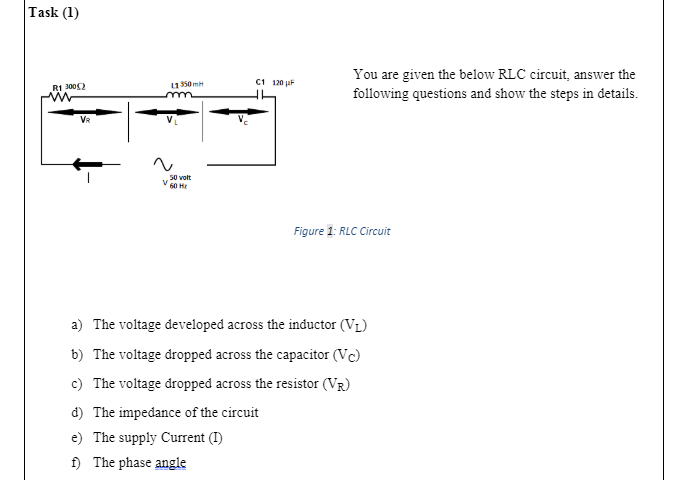
Transcribed Image Text:Task (1)
You are given the below RLC circuit, answer the
following questions and show the steps in details.
11350 mH
C1 120 uF
R1 3002
VR
50 volt
60 не
Figure 1: RLC Circuit
a) The voltage developed across the inductor (VL)
b) The voltage dropped across the capacitor (Vc)
c) The voltage dropped across the resistor (VR)
d) The impedance of the circuit
e) The supply Current (I)
f) The phase angle

Transcribed Image Text:Task (2)
You are given the below circuit, answer the following questions and show the steps of your solution in
details.
12
R1
7.7 KO
V2
5V
R2
13
V1
10 V
3.3 KO
14
15
V3
R3
1.5 KO
Figure 2: Electrical Circuit
a) Apply the scientific method to validate both Kirchhoff voltage law (KVL) and Kirchhoff current
law (KCL) for the above circuit to find I1, I2, I3 14, Is and Is. Show your steps:
b) Use circuit theorem to calculate the power consumed in R1
c) Calculate the voltage across R2
Expert Solution
This question has been solved!
Explore an expertly crafted, step-by-step solution for a thorough understanding of key concepts.

This is a popular solution!

Trending now
This is a popular solution!

Step by step
Solved in 6 steps with 10 images

Knowledge Booster


Learn more about
Need a deep-dive on the concept behind this application? Look no further. Learn more about this topic, electrical-engineering and related others by exploring similar questions and additional content below.Recommended textbooks for you
Delmar's Standard Textbook Of Electricity
Electrical Engineering
ISBN:
9781337900348
Author:
Stephen L. Herman
Publisher:
Cengage Learning

Power System Analysis and Design (MindTap Course …
Electrical Engineering
ISBN:
9781305632134
Author:
J. Duncan Glover, Thomas Overbye, Mulukutla S. Sarma
Publisher:
Cengage Learning
Delmar's Standard Textbook Of Electricity
Electrical Engineering
ISBN:
9781337900348
Author:
Stephen L. Herman
Publisher:
Cengage Learning
Power System Analysis and Design (MindTap Course …
Electrical Engineering
ISBN:
9781305632134
Author:
J. Duncan Glover, Thomas Overbye, Mulukutla S. Sarma
Publisher:
Cengage Learning