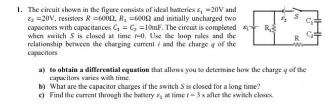
The circuit shown in the figure consists of ideal batteries &, =20V and Ez =20V, resistors R =6002, R, =6002 and initially uncharged two capacitors with capacitances C, = C2 =10mF. The circuit is completed R, when switch S is closed at time t-0. Use the loop rules and the relationship between the charging current i and the charge q of the capacitors R a) to obtain a differential equation that allows you to determine how the charge q of the capacitors varies with time. b) What are the capacitor charges if the switch S is closed for a long time? c) Find the current through the battery ɛ, at time t= 3 s after the switch closes.
The circuit shown in the figure consists of ideal batteries &, =20V and Ez =20V, resistors R =6002, R, =6002 and initially uncharged two capacitors with capacitances C, = C2 =10mF. The circuit is completed R, when switch S is closed at time t-0. Use the loop rules and the relationship between the charging current i and the charge q of the capacitors R a) to obtain a differential equation that allows you to determine how the charge q of the capacitors varies with time. b) What are the capacitor charges if the switch S is closed for a long time? c) Find the current through the battery ɛ, at time t= 3 s after the switch closes.

Related questions
Question
Transcribed Image Text:The circuit shown in the figure consists of ideal batteries &, =20V and
Ez =20V, resistors R =6002, R, =6002 and initially uncharged two
capacitors with capacitances C, = C2 =10mF. The circuit is completed R,
when switch S is closed at time t-0. Use the loop rules and the
relationship between the charging current i and the charge q of the
capacitors
R
a) to obtain a differential equation that allows you to determine how the charge q of the
capacitors varies with time.
b) What are the capacitor charges if the switch S is closed for a long time?
c) Find the current through the battery ɛ, at time t= 3 s after the switch closes.
Expert Solution
This question has been solved!
Explore an expertly crafted, step-by-step solution for a thorough understanding of key concepts.

Step by step
Solved in 3 steps with 4 images
