the display module. lghted when a logic , 7, 5, and 4, and "8" by lighting all seven seg- ogic 1 is applied to the corresponding input on a FIGURE 8-15 circuit Driving Seven-Segment Seven-Segment Indicator Module Inputs From n Toggle C- | Designed X 06 A- | Circuit 2 to be gage Learning 2014 Switches 4 5 7 8.A Design an 8-4-2-1 BCD code converter to drive a seven-segment indicator. The four inputs to the converter circuit (A, B, C, and D in Figure 8-15) represent an 8-4-2-1 binary-coded-decimal digit. Assume that only input combinations representing the digits 0 through 9 can occur as inputs, so that the combinations 1010 through 1111 are don't-cares. Design your ci gates and inverters A, B, C, and D will be available from toggle switches. . rcuit using only two-, three-, and four-input NAND . Try to minimize the number of gates required. The variables Use (not for 6. Use(not ) for 9. Any solution that uses 18 or fewer gates and inverters (not counting the four invert- ers for the inputs) is acceptable. 8.B Design an excess-3 code converter to drive a seven-segment indicator. The four inputs to the converter circuit (A, B, C, and D in Figure 8-15) represent an excess-3 coded decimal digit. Assume that only input combinations representing the dig- nt the siy unused combinations are don't-
the display module. lghted when a logic , 7, 5, and 4, and "8" by lighting all seven seg- ogic 1 is applied to the corresponding input on a FIGURE 8-15 circuit Driving Seven-Segment Seven-Segment Indicator Module Inputs From n Toggle C- | Designed X 06 A- | Circuit 2 to be gage Learning 2014 Switches 4 5 7 8.A Design an 8-4-2-1 BCD code converter to drive a seven-segment indicator. The four inputs to the converter circuit (A, B, C, and D in Figure 8-15) represent an 8-4-2-1 binary-coded-decimal digit. Assume that only input combinations representing the digits 0 through 9 can occur as inputs, so that the combinations 1010 through 1111 are don't-cares. Design your ci gates and inverters A, B, C, and D will be available from toggle switches. . rcuit using only two-, three-, and four-input NAND . Try to minimize the number of gates required. The variables Use (not for 6. Use(not ) for 9. Any solution that uses 18 or fewer gates and inverters (not counting the four invert- ers for the inputs) is acceptable. 8.B Design an excess-3 code converter to drive a seven-segment indicator. The four inputs to the converter circuit (A, B, C, and D in Figure 8-15) represent an excess-3 coded decimal digit. Assume that only input combinations representing the dig- nt the siy unused combinations are don't-

Introductory Circuit Analysis (13th Edition)
13th Edition
ISBN:9780133923605
Author:Robert L. Boylestad
Publisher:Robert L. Boylestad
Chapter1: Introduction
Section: Chapter Questions
Problem 1P: Visit your local library (at school or home) and describe the extent to which it provides literature...

Related questions
Question
help me with ques 8A
Transcribed Image Text:the display module.
lghted when a logic
, 7, 5, and 4, and "8" by lighting all seven seg-
ogic 1 is applied to the corresponding input on
a
FIGURE 8-15
circuit Driving
Seven-Segment
Seven-Segment Indicator
Module
Inputs From
n Toggle C- | Designed X 06
A- | Circuit
2
to be
gage Learning 2014
Switches
4
5
7
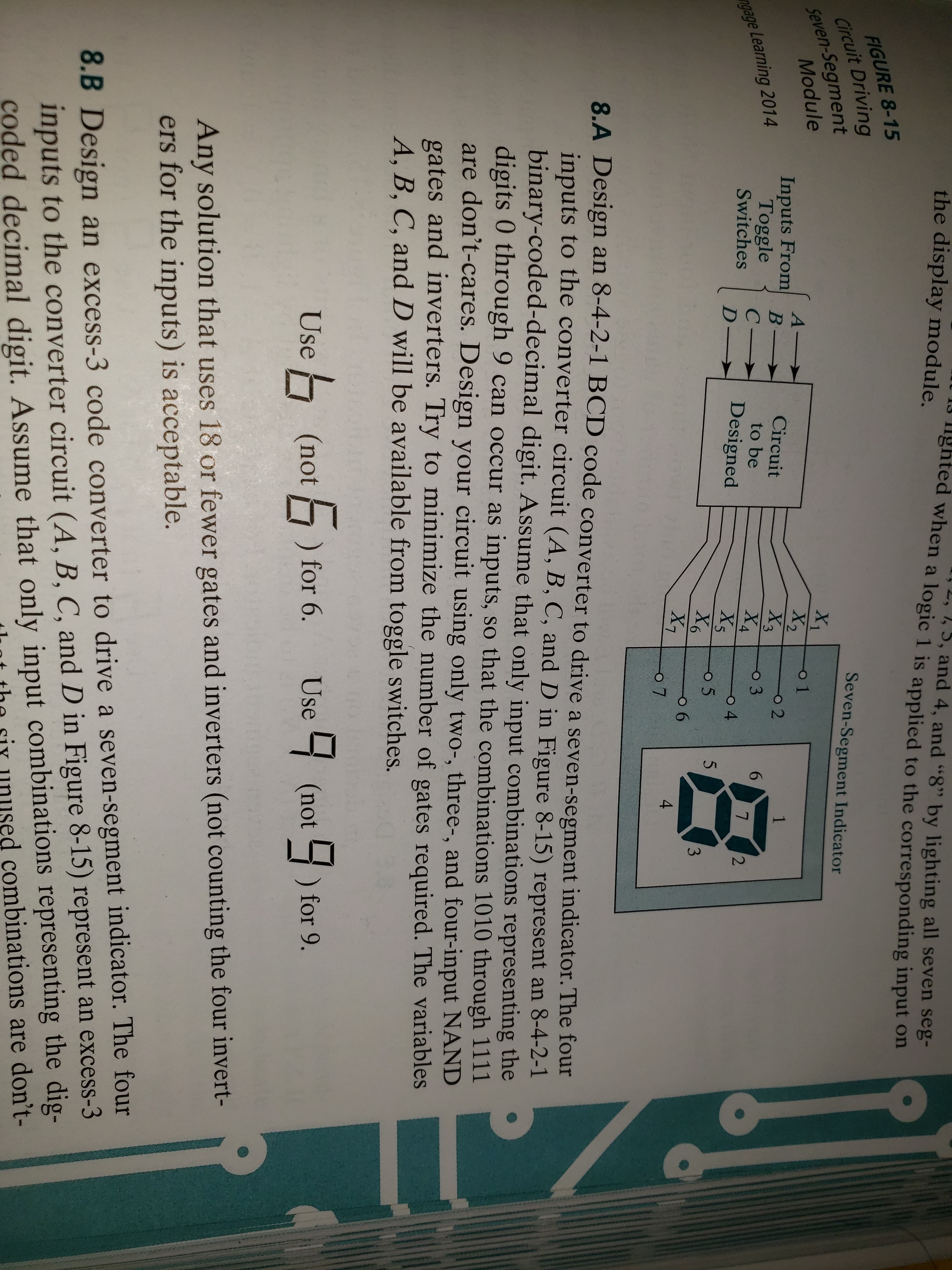
8.A Design an 8-4-2-1 BCD code converter to drive a seven-segment indicator. The four
inputs to the converter circuit (A, B, C, and D in Figure 8-15) represent an 8-4-2-1
binary-coded-decimal digit. Assume that only input combinations representing the
digits 0 through 9 can occur as inputs, so that the combinations 1010 through 1111
are don't-cares. Design your ci
gates and inverters
A, B, C, and D will be available from toggle switches.
.
rcuit using only two-, three-, and four-input NAND
. Try to minimize the number of gates required. The variables
Use
(not for 6. Use(not ) for 9.
Any solution that uses 18 or fewer gates and inverters (not counting the four invert-
ers for the inputs) is acceptable.
8.B Design an excess-3 code converter to drive a seven-segment indicator. The four
inputs to the converter circuit (A, B, C, and D in Figure 8-15) represent an excess-3
coded decimal digit. Assume that only input combinations representing the dig-
nt the siy unused combinations are don't-
Expert Solution
This question has been solved!
Explore an expertly crafted, step-by-step solution for a thorough understanding of key concepts.

This is a popular solution!

Trending now
This is a popular solution!

Step by step
Solved in 8 steps with 8 images

Knowledge Booster


Learn more about
Need a deep-dive on the concept behind this application? Look no further. Learn more about this topic, electrical-engineering and related others by exploring similar questions and additional content below.Recommended textbooks for you
Introductory Circuit Analysis (13th Edition)
Electrical Engineering
ISBN:
9780133923605
Author:
Robert L. Boylestad
Publisher:
PEARSON

Delmar's Standard Textbook Of Electricity
Electrical Engineering
ISBN:
9781337900348
Author:
Stephen L. Herman
Publisher:
Cengage Learning

Programmable Logic Controllers
Electrical Engineering
ISBN:
9780073373843
Author:
Frank D. Petruzella
Publisher:
McGraw-Hill Education
Introductory Circuit Analysis (13th Edition)
Electrical Engineering
ISBN:
9780133923605
Author:
Robert L. Boylestad
Publisher:
PEARSON
Delmar's Standard Textbook Of Electricity
Electrical Engineering
ISBN:
9781337900348
Author:
Stephen L. Herman
Publisher:
Cengage Learning
Programmable Logic Controllers
Electrical Engineering
ISBN:
9780073373843
Author:
Frank D. Petruzella
Publisher:
McGraw-Hill Education

Fundamentals of Electric Circuits
Electrical Engineering
ISBN:
9780078028229
Author:
Charles K Alexander, Matthew Sadiku
Publisher:
McGraw-Hill Education

Electric Circuits. (11th Edition)
Electrical Engineering
ISBN:
9780134746968
Author:
James W. Nilsson, Susan Riedel
Publisher:
PEARSON

Engineering Electromagnetics
Electrical Engineering
ISBN:
9780078028151
Author:
Hayt, William H. (william Hart), Jr, BUCK, John A.
Publisher:
Mcgraw-hill Education,