The figure below shows a circuit with two identical resistors and an ideal conductor Is the current through the central resistor more than, less than, or the same as that through the other resistor (a) just after the closing of switch S, (b) a long time after that, (c) just after S is reopened a long time later, and (d) a long time after that? You must justify your answers.
The figure below shows a circuit with two identical resistors and an ideal conductor Is the current through the central resistor more than, less than, or the same as that through the other resistor (a) just after the closing of switch S, (b) a long time after that, (c) just after S is reopened a long time later, and (d) a long time after that? You must justify your answers.

Chapter14: Inductance
Section: Chapter Questions
Problem 58P: Consider the circuit shown below. Find l1, l2and l3when (a) the switch S is first closed, (b) after...

Related questions
Question
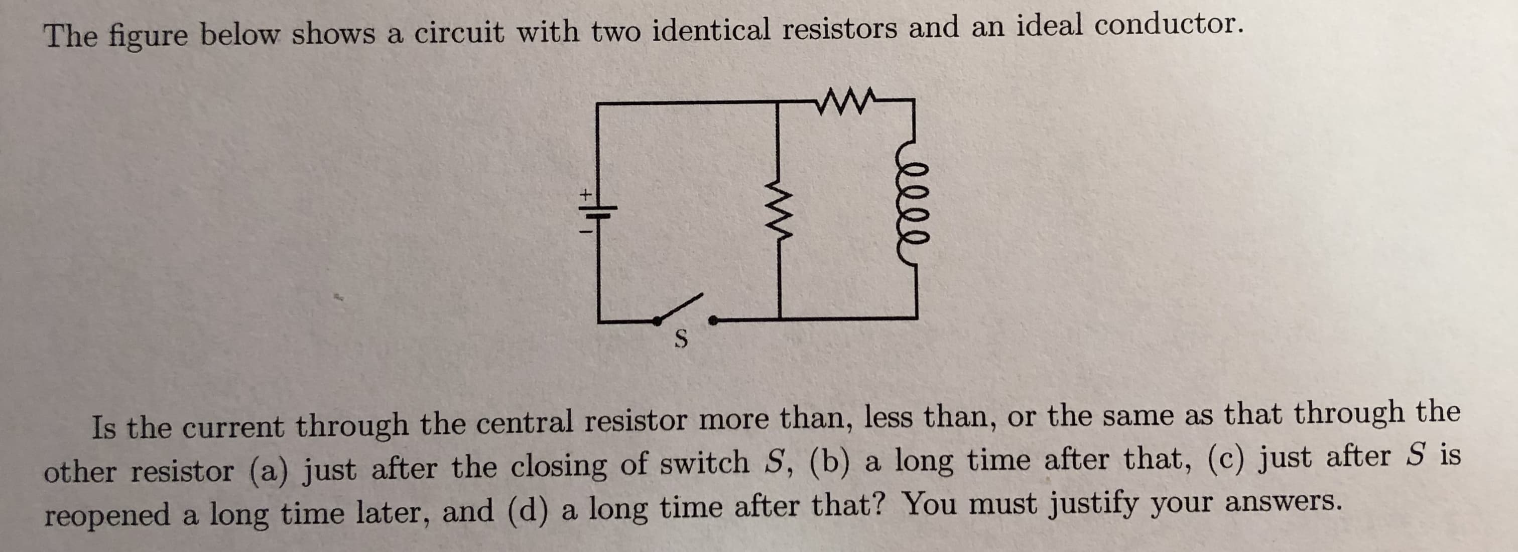
Transcribed Image Text:The figure below shows a circuit with two identical resistors and an ideal conductor
Is the current through the central resistor more than, less than, or the same as that through the
other resistor (a) just after the closing of switch S, (b) a long time after that, (c) just after S is
reopened a long time later, and (d) a long time after that? You must justify your answers.
Expert Solution
This question has been solved!
Explore an expertly crafted, step-by-step solution for a thorough understanding of key concepts.

This is a popular solution!

Trending now
This is a popular solution!

Step by step
Solved in 3 steps

Recommended textbooks for you