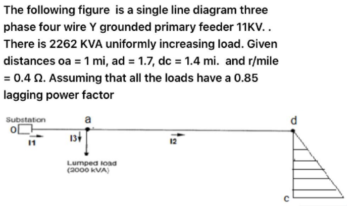
The following figure is a single line diagram three phase four wire Y grounded primary feeder 11KV.. There is 2262 KVA uniformly increasing load. Given distances oa =1 mi, ad = 1.7, dc = 1.4 mi. and r/mile = 0.4 N. Assuming that all the loads have a 0.85 lagging power factor Substation a d 13 12 Lumped load (2000 kVA)
Q: A dc two line distributor AB 600 metre long is fed at 440 V from substation A and at 430 V from…
A:
Q: For the power system its one line diagram is shown below: 1-Draw the reactance diagram for power…
A:
Q: 1.The primary conductor in the figure is one phase of a three-phase transmission line operating at…
A:
Q: Hw2.1-3: 3-phase, 2-winding, 12 MVA, 30/132 KV, star/delta, 50Hz transformer of equivalent leakage…
A: It is given that: MVA=12V1/V2=30/132 KVf=50 HzXl=17 ohmcosϕ=0.75
Q: 7. A single phase line is transmitting 1100 kW power to a factory at 11kV and 0.8 p.f lagging. It…
A: Here, we have given some information about a transmission line, So, we will first calculate the…
Q: The following data were obtained on a 2.5 MVA, 50-Hz, 19.1-kV:3.81-kV tested at 50 Hz: Voltage (V)…
A: Since we only answer up to 3 sub-parts, we’ll answer the first 3. Please resubmit the question and…
Q: Consider the above equivalent circuit of IM, A six pole, 250 volt(line to line), 60Hz, Y connected ,…
A: Dear student as per our guidelines we are supposed to solve only one question in which it should be…
Q: 3 Machine 2 Machine 1 Y A Two synchronous machines are connected through three-phase transformers to…
A: for the Figure Two synchronous machines are connected through three phase Transformers to a…
Q: Q5: A SL-G fault occurs on the low voltage side of a transformer that connects a motor to a…
A: Given data for generator, Given data for motor,
Q: Q3: A three phase, four wire, 208 volt, CBA system has a Y-Y connected load with A-6 , ZB-6230°, and…
A: In the question, Four wire 3 phase system given Phase sequence CBA. Find the line current and…
Q: A 3-phase transmission line operating at 33 kV and having a resistance of 5 Ω and reactance of 20 Ω…
A: A 3-phase transmission line operating at 33 kV and having a resistance of 5 Ω and reactance of 20 Ω…
Q: 2. For the electric power system shown in the figure below, draw the impedance diagram with all…
A: It is given that:
Q: Consider a simple power system: two generators (20MVA each at 13.2kV) running in parallel via a…
A:
Q: onsider the above approximate equivalent circuit for IM. A six-pole, 220Volt (line to line), 50Hz,…
A: Disclaimer: Since you have asked multipart questions, we will solve the first three subpart for…
Q: Three 10:1 transformers are connected delta to wye for stepping up the 2300-vilt three phase source.…
A:
Q: Consider the above equivalent circuit of IM. A six pole, 230 volt(line to line), 60Hz, Y connected…
A:
Q: Consider the above equivalent circuit of IM, A six pole, 250 volt(line to line), 60Hz, Y connected ,…
A: Dear student as per our guidelines we are supposed to solve only one question in which it should…
Q: A 3-phase transmission line operating at 33 kV and having a resistance of 5 Ω and reactance of 20 Ω…
A: A 3-phase transmission line operating at 33 kV and having a resistance of 5 Ω and reactance of 20…
Q: A 100 km Three-Phase 50 Hz transposed transmission line is çomposed of bundle of three ACSR,…
A: The power system has to transmit power from the generation side to the load side. For this purpose,…
Q: If 50 MVA, 50 Hz Synchronous generator supplying 50 MW with inertia constant 'H' = 2.5 MJ/MVA at…
A:
Q: From figure below, , if 3 phase bolted fault occurs at point 2. Calculate i) Rating of CB's ii) Volt…
A:
Q: Q1(a) An open-circuit line voltages of 8530 V were produced by a three-phase synchronous generator…
A: The solution is given below
Q: The single-line diagram of a three-phase power system is shown in the below figure. Equipment…
A: Given base parameters for zone 1-2 MVAb = 1000 MVA KVb =765 kV to determine positive negative and…
Q: 1. The open circuit characteristic of a 3-phase 10 MVA, 13 kV, 50 Hz, Star connected synchronous…
A: The values of saturated synchronous impedance do not change but vary in sensitivity and strength…
Q: Non-Reactive Loads of 10kW, 20kW and 12kW are connected between the neutral and the red, yellow and…
A: Line voltage =400V Phase voltage=4003=230.95VPR=Vph2R ∴ Resistance in R phase=Vph2PR=4003210k…
Q: A single phase transmission line is delivering 460 kVA load at 10 kV. Its resistance is 6 Ω and…
A: Part (1): The current in the transmission line is determined as: P=VrmsIrmscosθ460 kVA=10…
Q: From a three- phase four wire distribution system, will it be possible to get single phase supply?…
A: There are three major stages of the Power system Generation System - Generates power at the plant.…
Q: The single line diagram of a three-phase power system is shown in Figure 1. Select a common base of…
A:
Q: Electric Machine; Check image, all question there. Consider the above approximate equivalent…
A: Given Data: R1=0.5Ω , R2=0.25 Ω, X1=0.75 Ω, X2=0.5 Ω, Xm=100 Ω, Rc=500 Ω
Q: System Model and Per Unit T1 Line T2 BE ji0/km BE 31.25miles 3C Impedance Load R1.jXi.-0.1+j0.5 p.u.…
A: The single line diagram is shown below: (a) The value of the base MVA and Base KV will be 30 and 13…
Q: For a square-shaped distribution substation service area, assume that the substation is served by…
A: “Since you have posted a question with multiple sub-parts, we will solve first three sub-parts for…
Q: A 3-phase short circuit fault at point E in a plant with single line representation below. consists…
A: In this question we need to find a fault current at point E.
Q: 2. The one-line diagram of a power system is shown in the figure. The three-phase power and…
A:
Q: A three phase,Y connected, 215 V (line to line), 7.5 kW, 60 Hz, three pole IM has the following…
A:
Q: Problems 1. Two synchronous machines are connected through three phase transformer to the…
A: Given: Machine 1 and 2:100 MVA, 20kV, X1=X2=20%X0=4%, Xn=5%T1and T2:100 MVA, 20/345kV, X=8%Line:…
Q: Question 3: For the power system as shown, the line impedance is 4+j 3 ohms (primary) and zone 1 is…
A: Given ZL=4+j3 ΩCT ratio=500:5 AVT ratio=20,000:69.3 VRated voltage=34.64 KVRated MVA=24 MVA Zone 1…
Q: ) Consider a 3-phase, 33 kV transformers with N1:N2 = 900:150. Calculate the secondary line voltage…
A: a 3-phase, 33 kV transformers N1:N2 = 900:150. Calculate the secondary line voltage on no load…
Q: A workshop from a 231/400 V transformer center with a 3-phase and four-conductor underground cable…
A: Transformer: It is a static device, which converts the electrical power from one circuit to another…
Q: One-line diagram of a power system is shown below. Relevant details are mentioned below. Generator:…
A: Consider the generator rating as a base. The generator rating is given as 100 MVA and 11 kV. For the…
Q: A load of 145 MW at a power factor of 0.75 lagging can be delivered by a 3-phase transmission line.…
A:
Q: 1. Explain the advantages and disadvantages of Single Phase and Three Phase Power Supply. Justify…
A: Sr. No. Single-phase power supply Three-phase power supply 1 One live conductor Three live…
Q: 1. Repeat Example 4.2, parts (a) and (b), assuming a three-phase 34.5 kV wye-grounded feeder main…
A: PArt a and part b of Example 4.2 is repeated for the following data as shown below
Q: Question 1 On figure 1 below is a single-phase ring distributor fed from point O at 400v, 50HZ.…
A: Given circuit- In this question, the value of per impedance of the distributor section BC is…
Q: TI T2 M 50 +j 100 ohm AY YA Lood
A: Given the two-machine system of Figure below, we select quite arbitrarily a base voltage of 161 kV…
Q: (Q.2) For the following network, calculate the fault currents (IFı, IF2, IF3 and IF.) in pu and in…
A: There will be three sequence networks in the given power system- Positive-sequence network…
Q: Line impedances for the power system shown in Figure 1 are Z12 = Z23 = 3.0 + j40.0 Ω, and Z24 = 6.0…
A: Any obstacle or measurement of the resistance of an electric current to the energy flow when voltage…
Q: le, 230 volt (line to line) 60 Hz. Y con 5 2, Ra - 0.25 2, X1 = 0.75 2, on and windage loss is 150…
A: Since you posted a question with multiple sub-parts. We will solve the first three sub-parts for…
Q: 3 Consider the one-line diagram of power system shown below; if a bolted three-phase fault (F1)…
A: Note: We are authorized to answer three subparts at a time, since you have not mentioned which part…
Q: Three 1:10 transformers are connected delta-wye for stepping up the 2,300-volt three phase source.…
A:
Find total loss(w) from d to c .
Step by step
Solved in 3 steps
- Figure 3.32 shows the oneline diagram of a three-phase power system. By selecting a common base of 100 MVA and 22 kV on the generator side, draw an impedance diagram showing all impedances including the load impedance in per-unit. The data are given a follows: G:90MVA22kVx=0.18perunitT1:50MVA22/220kVx=0.10perunitT2:40MVA220/11kVx=0.06perunitT3:40MVA22/110kVx=0.064perunitT4:40MVA110/11kVx=0.08perunitM:66.5MVA10.45kVx=0.185perunit Lines I and 2 have series reactances of 48.4 and 65.43, respectively. At bus 4, the three-phase load absorbs 57 MVA at 10.45 kV and 0.6 power factor lagging.The units of admittance, conductance, and susceptance are siemens. (a) True (b) FalseDetermine the bus admittance matrix (Ybus) for the three-phase power system shown in Figure 6.23 with input data given in Table 6.11 and partial results in Table 6.12. Assume a three-phase 100 MVA per unit base. TABLE 6.11 Bus input data for Problem 6.20 TABLE 6.12 Partially Completed Bus Admittance Matrix (Ybus) for Problem 6.30
- PowerWorid Simulator case Problem 3_60 duplicates Example 3.13 except that a resistance term of 0.06 per unit has been added to the transformer and 0.05 per unit to the transmission line. Since the system is no longer lossless, a field showing the real power losses has also been added to the oneline. With the LTC tap fixed at 1.05, plot the real power losses as the phase shift angle is varied from 10 to +10 degrees. What value of phase shift minimizes the system losses?Which termination would result to a phase change of 180 degrees at the load if Zo = 100 ohm? a. 50 ohm b. short circuit c. 75 ohm d. all of these What is the purpose of impedance matching? a. maximum return loss b. maximum SWR c. maximum load power d. maximum reflection A short piece of transmission line that may be open or shorted and used for impedance matching purposes. a. converter b. decoder c. stub d. transformerRefer to the 5-bus data given below. Sbase = 400 MVA, the base voltage is 15.0 kV for buses 1 and 3, and 345 kV for buses 2, 4, 5. Note that 1-5 and 3-4 are 15/345 kV transformers.a) Draw a one-line diagram of the power system.b) Find the elements Y23, Y43, Y11 Y33 of the system bus admittance matrix.
- Shown are two buses connected via a transmission line. Connected to Bus 1 is a generator(modelled as a voltage source V1), and to Bus 2 is a generator( with Voltage V2) and a load. The line impedance Z = R + jX is not known. Three-phase load is forecasted as 100MW + 60MVar. Generator at Bus 2 is scheduled to deliver 40MW and its excitation is adjusted for the machine to deliver 55 MVar. Voltage at Bus 1 is 241 KV angle 10 deg, while voltage at bus is 230 kV; use V2 as the reference for all angles. 1. What is the current (RMS) in amperes drawn by the load connected to Bus 2? 2. How much real power (in MW) is delivered by the generator connected to Bus 1? 3. What is the total real power loss along the line, in percent of the load? 4. What is the X/R Ratio of the line impedance?An 11 KV, 3-phase transmission line has a resistance of 1.5 Ω and reactance of 4 Ω per phase.Calculate the percentage regulation and efficiency of the line when a total load of 5000 KVA at 0.8 lagging power factor is applied at 11KV at the distant end.Line impedances for the power system shown in Figure 1 are Z12 = Z23 = 3.0 + j40.0 Ω, and Z24 = 6.0 + j80.0 Ω. Reach for the zone 3 B12 impedance relays is set for 100% of line 1–2 plus 120% of line 2–4. (a) For a bolted three-phase fault at bus 4, show that the apparent primary impedance “seen” by the B12 relays is Zapparent = Z12 + Z24 + (I32/I12)Z24 where (I32/I12) is the line 2–3 to line 1–2 fault current ratio. (b) If |I32/I12| > 0.20, does the B12 relay see the fault at bus 4?
- The single line diagram of a power system is shown below. Load represented as impedance, (13.2) kV voltage It draws 60 MVA power from the system when it is below and (0.9) back power factor. Generators and transformers The related electrical parameters are given below. According to this; a) Calculate all impedances in this given circuit in pu and draw the equivalent impedance diagram of the circuit. (Select the base values as 100 MVA and 13.8 kV.) b) Since the voltage values of the generators are given as E1=1.1∟0° pu and E2=1.25∟10° pu, Calculate the value of the voltage (V1).Two similar star-grounded synchronous generators, one of which has its star point grounded, supply 11 kV three-phase busbars. An 11/66 kV delta/star connected transformer with the star point grounded is supplied from the busbars. The impedances referred to 11 kV, are as given below : Generator Transformer Impedance to positive-sequence currents j3.0 Ω j 3.0 Ω Impedance to negative-sequence currents j 2.0 S2 j3.0Ω Impedance to zero-sequence currents j 1.012 j3.0Ω Determine the fault current for an LG fault (a) on a busbar, and (b) at an hv terminal of the transformer. (c) Find also the voltage to ground of the two sound busbars in case (a).What load can be delivered by a 3-phase overhead line 5 km long with a pressure drop of 10%. Given that the station voltage is 11 kV, resistance per km of each line 0.09 Ω, reactance per km 0.08 Ω and the power factor of the load 0.8 lagging. ..