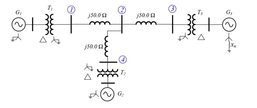
The four-bus power system in Figure 2 has following equipment parameters: G1: 500 MVA 13.8 KV, xd"=x1=x2=0.20, x0=0.10pu G2: 750 MVA, 18 kv, xd"=x1=x2=0.18, x0=0.09pu G3: 1000 MVA, 20 kv, xd"=x1=0.17, x2=0.20, x0=0.09pu T1: 500 MVA, 13.8/500 kv, delta-wye, x=0.12pu T2: 750 MVA, 18/500 kv, delta-wye, x=0.10pu T3: 1000 MVA, 20/500 kv, delta-wye, x=0.10pu Each Line: X1 = 50 Ω; X0 = 150 Ω All per-unit reactance values are given on the respective equipment rating (voltage and power) as the base. The inductor connected to generator G3 neutral has a reactance of 0.028 Ω. (a) Draw the zero- positive- and negative-sequence reactance diagrams using a 1,000 MVA, 20 kV base in the zone of generator G3. Neglect ∆ - Y transformer phase shift. (b) Faults at bus 1 are of interest. Determine the Thevenin equivalent of each sequence network as viewed from the fault bus. Prefault voltage is 1.0 pu. Prefault load currents and ∆ - Y transformer phase shift are neglected.


The four-bus power system in Figure 2 has following equipment parameters:
G1: 500 MVA 13.8 KV, xd"=x1=x2=0.20, x0=0.10pu
G2: 750 MVA, 18 kv, xd"=x1=x2=0.18, x0=0.09pu
G3: 1000 MVA, 20 kv, xd"=x1=0.17, x2=0.20, x0=0.09pu
T1: 500 MVA, 13.8/500 kv, delta-wye, x=0.12pu
T2: 750 MVA, 18/500 kv, delta-wye, x=0.10pu
T3: 1000 MVA, 20/500 kv, delta-wye, x=0.10pu
| Each Line: X1 = 50 Ω; | X0 = 150 Ω |
All per-unit reactance values are given on the respective equipment rating (voltage and power) as the base. The inductor connected to generator G3 neutral has a reactance of 0.028 Ω.
(a) Draw the zero- positive- and negative-sequence reactance diagrams using a 1,000 MVA, 20 kV base in the zone of generator G3. Neglect ∆ - Y transformer phase shift.
(b) Faults at bus 1 are of interest. Determine the Thevenin equivalent of each sequence network as viewed from the fault bus. Prefault voltage is 1.0 pu. Prefault load currents and ∆ - Y transformer phase shift are neglected.


Trending now
This is a popular solution!

Step by step
Solved in 7 steps with 6 images


