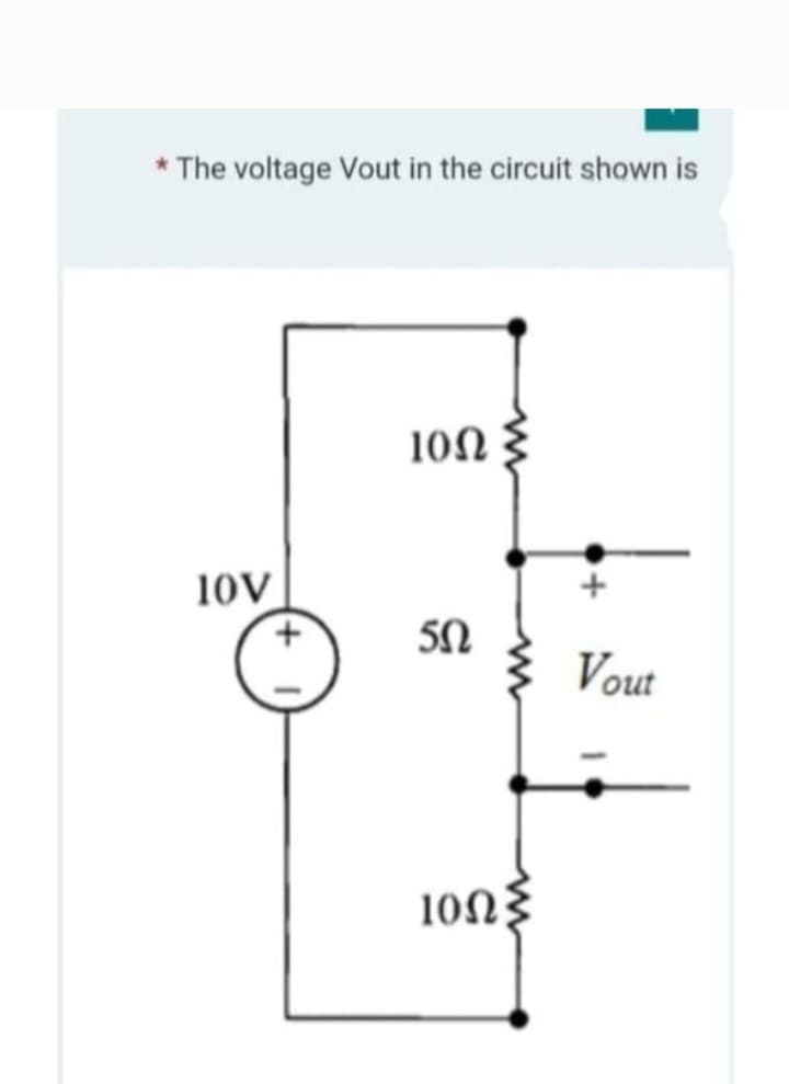
* The voltage Vout in the circuit shown is


Q: Based on the signals below, find the Fourier transform of x(t) for (a)-(e). -2 x(t) n 2 (a) -2 -1…
A: As per Bartleby guideline we need to answer the first question only. Kindly repost the rest…
Q: Q1] for the following circuit choose the correct answer Assume that the circuit operates at w = 50…
A:
Q: ܕܒܓ ܝܘ c(t) =1=e7r cos @at 1-g -sin out
A:
Q: An 800 kV transmission line has a maximum power transfer capacity, P, it is operated at 400 kV with…
A: Let Vs be sending end voltage, VR be the receiving end voltage and X be the series…
Q: 3. A bode plot of (1+jWT) has a) Slope of 20dB/decade and phase angle of tan ¹(wT) b) Slope of…
A: We need to find out the slope and phase for given transfer function .
Q: Refine the algorithm successively to get step by step detailed algorithm that is a computer…
A:
Q: The BEST choice electronic device to turn a device at a particular voltage is a/an _____. A. PUT B.…
A: the correct option would be SCS. Particular voltage can be obtained by adjusting firing angle of scs…
Q: Question 47 If a resistor is dissipating 1/4 W, it can supply 1/4 W to the load. True False
A:
Q: A diode is an example of ___ switch. A. SPDT B. passive C. active D. DPDT
A: Diodes always have some barrier potential across it. It is represented by a drop of 0.7V or 0.3V…
Q: B- Consider the differential amplifier in Fig. 1. Where, Ir=1mA, Rc-10 KM2, VBE = 0.7 V (1). For Var…
A:
Q: Q2) For the circuit shown in Fig. 2 describe the output voltage and draw the waveform if the pulse…
A: Given circuit,
Q: P1: By inspection obtain node-voltage equations (GV=I) and write MATLAB commands and provide…
A:
Q: From the curcuit given below, determine the total amount of power in the series circuit. 50 V 5Ω 292…
A:
Q: 2. Design a clamper circuit to perform the function indicated. Vin + t1 Vin -10 V 10 V DESIGN Si…
A: We need to design the given clamper circuit for given input and output voltage. We will design it…
Q: R₁ R₂ R3 R4 Rs R6 R7 RA W R₂ R₂ W R₁ 30 V R₁2 R₁3 R₁4 75 Ω 25 Ω 50 Ω R₁1 50 Ω 25 Ω 75 Ω Fig. 3.1 W…
A: Given: A network with 30 v dc supply along 14 resistance with various values connected in variety…
Q: A unity feedback system, having an open loop gain G(s)H(s) = K(1-s) (1+s) A IKI > 1 B K> 1 C|K| < 1…
A:
Q: A 160 resistor, an 8302 inductive reactance, and a 20 capacitive reactance are in series. A 120V…
A: We need to find out current for given series RLC circuit
Q: 5. Deterime the total current I if terminals A and B is shorted. 100 V 12 ohms a b 28 ohms 20 ohms…
A: 5) To determine the total current I in the circuit if the terminals A and B are shorted
Q: 40 m 10 V Figure 6.5 1202 Select one: A. 4 V B. 10 V C. 6 V D. 8 V + V₂ See Figure 6.5. What is the…
A: We need to find out the open circuit voltage for given circuit
Q: wo shunt generators and a battery are all connected to common bus-bars. The open circuit voltage of…
A: It is given that: VB=247 VEg1=Eg2=250 VRa1=Ra2=0.12 ΩRf1=Rf2=100 ΩIL=40 A
Q: What is the output of following program: X= -3.5 Y= Sgn (-3.5) Print Y 3.5-O 3.5 O 10 1-0
A: f=sgn(a) f=1 when a greater than 0 f=0 when a is equal to 0 f=-1 when a is less than 0
Q: OBTAIN A NUMERICAL VALUE FOR THE POWER ABSORBED вч ЕАСH Егембит IN THE стешет вегоw. (SINGLE-L00P…
A:
Q: Find the percent modulation of an AM wave whose total power content is 2500 W and whose sidebands…
A:
Q: On full-load a 300 V series motor takes 90A and runs at 15 rev/s. The armature resistance is 0.1 ohm…
A: Given- For series motor- Voltage at terminal = 300 V Current = 90 A Speed = 15 rev/sec Armature…
Q: Write a function using the block diagram shown below: X y X y' o I f
A:
Q: The equivalent resistance between points A and B:(shown in figure) is? C r www B wwww
A: Solution !!
Q: An 800 kV transmission line has a maximum power transfer capacity, P, it is operated at 400 kV with…
A: Given- 800 kV transmission line, Maximum power transfer capacity=P, 400 kV operation voltage, To…
Q: A power supply provides 400 watts to a load and is 80% efficient. In 24 hours how many…
A: Given: Power output, Pout=400 W. Efficiency, η=80%=0.8 . Time, t=24 hours.
Q: PROBLEM #9 IN THE CIRCUIT BELOW, ONLY THE VOLTAGE UX IS OF INTEREST. SIMPLIFY THE CIRCUIT USING…
A:
Q: A music signal has frequency components from 15 Hz to 30 kHz. If this signal could be used to…
A: Frequency components of music signal = 15 Hz - 30 kHz Carrier frequency fc = 1.2 MHz We have to…
Q: A 20-pole, star-connected, three-phase alternator rotates at 300 r.p.m. The armature has 360 slots…
A:
Q: .( A balanced A-connected resistive load of 8500 kW is connected to the low voltage, A-connected…
A:
Q: For an n-channel JFET, VGs(om=-8V and Ipss=7 mA. Determine the value of VGs required to set up ID of…
A: Use drain current equation of jet to determine value of VGS.
Q: Draw a block diagram given the function shown below: a. F = A B + C b. F=XY+X'Y + Y' Z C. (A + B')…
A: Given that boolean expressions to implement block diagrams
Q: A 3-phase 3-wire supply feeds a load consisting of three equal resistors connected in star. If one…
A: Given data, 3-phase 3-wire Supply:- Three-wire ac power circuits are used for three-phase power,…
Q: 2. V Min 0 in the standing wave pattern a) Kr=0 b) Kr=+0.5 c) Kr=±0.8 d) Kr=+1
A: SWR= (Vmax/Vmin)=(1+|Kr|)/(1-|Kr|) Where SWR= Standing wave ratio
Q: The armature of a separately-excited DC generator has 0.06 effective resistance. Each brush has an…
A: Given- For separately excited dc generator- Armature resistance = 0.06 ohm Brush resistance= 0.015…
Q: b) The reactance X of capacitance =jwc O True O False
A: reactance of capacitor X = 1j2πfc ohms . where , f is frequency . and c is capacitance in Farads .
Q: Write a function using the block diagram shown below
A: The given gate diagram is shown below,
Q: Obtain a realization of a full-adder using any combination of gates from the following ICs: 7400,…
A: Introduction: The full adder is the adder that adds three inputs and produces two outputs.Full…
Q: Q4: (answer in phasor form) V = 10 cos 4t b) i=....... Your answer i 592 www 0.1 F +41
A: We need to find out the current for given circuit
Q: Your turn: Determine V3 employing voltage division 6 Volt + 1Ω 202 www + V3 www +51 5 402 202 15+ V₂
A: This is a basic problem of voltage division rule of circuit. The solution is given in the next step
Q: Feedback & Control Systems - State-Space Representation Write the state-space representation of the…
A: The set of all potential and recognized states for a system is known as state space. Each distinct…
Q: Determine io from the given circuit below. www 2.2 Ω ہے 500 V 200 io www 46 Q ww 50 Q www 30 Ω 9Q
A:
Q: Q1] for the following circuit choose the correct answer Assume that the circuit operates at @= 50…
A: Given: A network with various elements. To find: Input impedance, Zin Note: We'll use series and…
Q: For a boost converter operating in continuous conduction mode, when the dc input voltage is 10…
A:
Q: 2.14 Calculate the value of I in the circuit in Fig. P2.14. m
A:
Q: "A coaxial cable has a foam polyethylene insulator whose velocity factor is 0.7. If the inner…
A:
Q: Q- A digital-to-analog converter with a full-scale output voltage of 3.5V has a resolution close to…
A: Given data- Full scale output voltage- Vfo=3.5 V, Resolution=14 mV, To Find- The bit size (n).
Q: Solve the emitter voltage of a voltage-divider bias circuit with Vcc=9V, R1=560k ohms, R2=560k ohms,…
A: Types of biasing for Transistor Fixed bias Self bias Voltage divider bias Collector bias Emitter…


Step by step
Solved in 2 steps


- In the circuit given below, R = 130 kΩ. Find the voltage v0.Va = 30V, Vb = 45V, Ic = 12mA. The circuit is in dc steady state. Use superposition. Considering ONLY the contribution of the voltage source, Va . Determine V1. Enter your answer in V rounded to one decimal place.A series circuit of two pure elements has an applied voltage of 200sin(100t+30)V. Determine the resulting steady-state current of the two elements are:a) R = 300 L =2.5 Hb) R = 400, Xc= 150 c) R = 250, C = 100u d) R = 120, Xl=300
- 1.a. What circuit is shown on the image above? 1.b. What is the gain? 1.c. If R2 is 40x higher than R1 what will happen to node 2? Provide waveform and explain why it happens. 1.d. Modify the circuit to have an overall gain of 2. Provide photos.Write an expression for the output voltage vo(t) ofthe circuit shown if R1 = 1 k , R2 =2 k , R3 =47 k , v2(t)=(0.01 sin 3770t) V, andv1(t)=(0.04 sin 10000t)V. Write an expression forthe voltage appearing at the summing junction (v−).In the circuit given below, R = 40 Ω. Identify v(t) for t > 0. a) v(t) = 6 cos(0.5t) V b) v(t) = 12 cos(0.5t) V c) v(t) = 6 sin(0.5t) V d) v(t) = 3 sin(0.5t) V
- USE Current Divider Theorem. provide the tran func the input is V(s)a. output is 1 ohm resistorb. output is voltage acros inductorif you have answered this question pls do not reanswer, I just need confirmation. Va = 26V, Vb = 42V, Ic = 10mA. The circuit is in dc steady state. Use superposition. Considering ONLY the contribution of the voltage source, Va. Determine I3. Enter your answer in mA rounded to one decimal place.Find the value of R, so that R ab = 11Ω
- Q1 Find the Norton equivalent circuit for the following circuit with respect f0 the terminals ab using Multsim program with the values that are shown on the circuit M 25V 60 40 50 1ov RL 250 30A source voltage is connected across a 10ohm resistor. What is the la place transform of its currentExampleConsider the following electrical system as shown in the following figure. This circuit consistsof resistor, inductor and capacitor. All these electrical elements are connected in series. Theinput voltage applied to this circuit is vi and the voltage across the capacitor is the outputvoltage vo. Find vo/vi ?